1
\$\begingroup\$

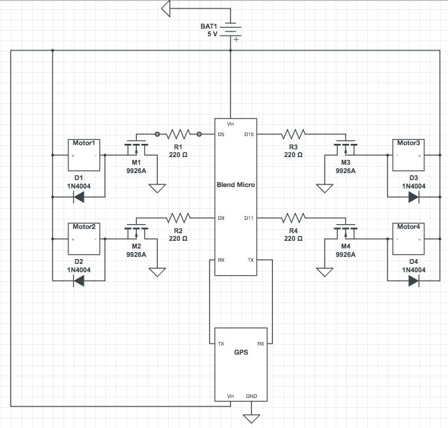
I am working on a Arduino based quadcopter. The Arduino being used is a Blend Micro. Not shown in the following diagram are 4 infrared sensors, 1 ultrasonic sensor and a 9 axis accelerometer.

Drone Wiring

The issue is that when the propellers are spinning the GPS "freaks out." The fix light flashes randomly as opposed to 1Hz as it does when the motors are not spinning.

If I had to make a guess it would be that the current passing through the snubber diodes does not completely re-enter the respective motors, causing fluctuations in the voltage attached to Vin of the GPS. I do not know if this correct and if it is, I am not entirely sure how to fix it. Perhaps a voltage regulator?

Edit: The GPS module is the "Adafruit Ultimate Gps"

\$\endgroup\$
2
  • \$\begingroup\$ Do you have a scope? You could monitor the Vin of the GPS module. \$\endgroup\$ Commented Apr 1, 2016 at 16:25
  • \$\begingroup\$ Just checked, the voltage drops on the GPS when the motors are turned on. Goes from around 5v to 4.8v with 2 motors running \$\endgroup\$
    – SMD01
    Commented Apr 1, 2016 at 16:32

1 Answer 1

2
\$\begingroup\$

You need, at a minimum, a large amount of bulk decoupling on your power rails. The motor driver is going to be wreaking havoc on your supply rails, and the GPS does not like this.

Better still, use two different rails, one for the motors, and one for the logic (GPS, IMU, MCU, etc). Even though the GPS has (if I read correctly) an onboard 3V3 regulator, you should try to keep your motors as electrically "far away" as possible from everything else.

I doubt you've actually got a 5V battery as your schematic says. If it's a regulator, run the motor driver directly from the battery, and regulate only the logic rails. If it's a battery, adding a regulator should help. If you put a scope on the power supply rails while this thing is running, you will quickly find out if the rails are the problem. If it's not noise from the motor drivers/motors, you might be drawing more current than the battery can provide (and causing the supply to droop).

\$\endgroup\$
2
  • \$\begingroup\$ Yea the battery isn't a single 5v, it's a 3.7v and a 1.3v in series. Also, as you said, when the motors run, the input voltage to the GPS does indeed drop. To achieve what you are describing would I need 2 power supplies, 1 for the motors, and the other for everything else? \$\endgroup\$
    – SMD01
    Commented Apr 1, 2016 at 16:50
  • \$\begingroup\$ I'm curious, what sort of 1.3V battery are you using? Yes, splitting power supplies is the easy solution, but if the supply is only dropping to 4.8V and it's stable, it shouldn't be a problem as the GPS supply range is 3V3-5V0, so noise rather than droop would be an issue. \$\endgroup\$
    – uint128_t
    Commented Apr 1, 2016 at 18:22

Your Answer

By clicking “Post Your Answer”, you agree to our terms of service and acknowledge you have read our privacy policy.

Not the answer you're looking for? Browse other questions tagged or ask your own question.