0
\$\begingroup\$

I've some problem using together TLL and CMOS integrated. I'm developing a project and only now I discovered that the two standards can create troubles together.

So I decided to use only TTL chips. Luckily I can also use HCT integrated, that are bot compatible with TTL and CMOS.

I'm not sure about compatibility only about one chip... the M48Z02 (datasheet). It is a 5V, 16 Kbit ZEROPOWER SRAM. In the datasheet it is also written:

Pin and function compatible with JEDEC standard 2 K x 8 SRAMs

Does it mean something about the compatibility with TTL technology?

If not, where can I find information about the compatibility between M48Z02 and TTL technology?

Any help you can provide will be really appreciated.

\$\endgroup\$
3
  • 1
    \$\begingroup\$ TTL is about logic levels. So look what voltages the part is working with and decide. \$\endgroup\$
    – Eugene Sh.
    Commented Apr 8, 2016 at 19:30
  • \$\begingroup\$ @EugeneSh. Thank you, should I delete this answer or if you want, put an answer and I'll accept it \$\endgroup\$
    – xdola
    Commented Apr 8, 2016 at 19:46
  • \$\begingroup\$ It's up to you. If you can compose a good answer yourself, such that people could benefit from it in the future - do it. Or wait for someone to come up with such an answer. Or just wait for upvotes/downvotes to see if people find this question useful :) \$\endgroup\$
    – Eugene Sh.
    Commented Apr 8, 2016 at 19:49

1 Answer 1

1
\$\begingroup\$

As Eugene Sh. said, TTL/CMOS problem is about logic level.

If fact the two different technologies use different voltage level to send logic high signal (1) or low signal (0).

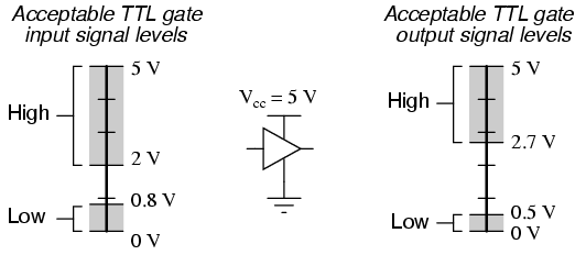
Here an image (from allaboutcircuits.com) that can explain this concept:

acceptable TTL gate input/output signal level

In the M48Z02 datasheet it is written:

|      Parameter      |  Min  |   Max   | Unit |
------------------------------------------------
| Input low voltage   | –0.3  |   0.8   |  V   |
| Input high voltage  |  2.2  | Vcc+0.3 |  V   |
| Output low voltage  |       |   0.4   |  V   |
| Output high voltage |  2.4  |         |  V   |

Putting data together, during communication from a TTL chip to M48Z02:

  1. TTL -> M48Z02:

    • Logic 0: communication ok, 0 > –0.3 and 0.5 < 0.8
    • Logic 1: communication ok, 2.7 > 2.2 and 5 < Vcc+0.3

During communication from M48Z02 to TTL:

  1. M48Z02 -> TTL:

    • Logic 0: communication ok, 0.4 < 0.8
    • Logic 1: communication ok, 2.4 > 2

In conclusion, they can communicate correctly.

\$\endgroup\$

Your Answer

By clicking “Post Your Answer”, you agree to our terms of service and acknowledge you have read our privacy policy.

Not the answer you're looking for? Browse other questions tagged or ask your own question.