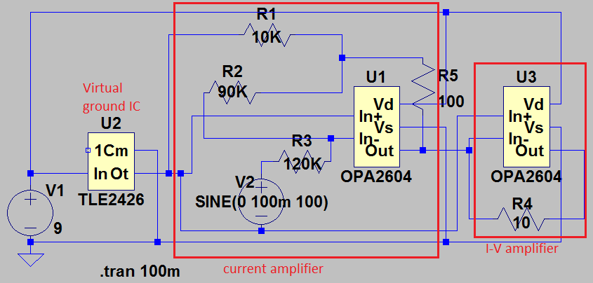
Figure shown above is the current amplifier circuit with the output current feeding into the transimpedance amplifier (I-V amplifier). I'm using a 100mV ac signal and 120 Kohm resistor to produce a 0.833 uA. The current amplifier circuit then amplify this input current by a gain of 10 to 8.33 uA. The output current from the current amplifier circuit is then feed into the I-V amplifier circuit to measure the voltage corresponding to the current. Using the feedback resistor(R4) of 10 ohm, I expected the output voltage to be around 83 uV. But, the current across R4 resistor is not 8.3 uA, instead it is 20mA. I'm not sure why I'm getting different current value. Also, i'm using the virtual ground IC to produce virtual ground of value 4.5 V. Could someone help me to understand what is wrong with this circuit?
2 Answers
U1 will produce a voltage at the output to balance the input current, which is V2/120K, since the input of U1 is at virtual ground. That output voltage will be about -90/120 times V2. So if V2 is 100mV peak, you'll see about 75mV peak at the output of U1.
You are feeding that voltage directly into the inverting input of U3 so you see the two outputs fighting each as they hit their respective current limits (the 10 ohm resistor won't make much difference). U3's output will try to drive its input to 0V (relative to the rail splitter output).
I think you don't clearly understand what a transimpedance amplifer does (convert input current to voltage).
-
1\$\begingroup\$ Thank you for the explanation. I just forgot to reference the virtual ground, so i was getting wired measurement all the time. when i referenced the output voltage measurement to virtual ground, im getting all the expected. And, I removed the I-V amplifier, as it is not needed. \$\endgroup\$– rajkCommented Apr 9, 2016 at 23:24
Start by disconnecting U3. Then the output of U1 is a voltage, approximately 75 mV. While the current in the op amp feedback loop is about 833 uA, this current is not reproduced in U3 when you connect it. Why should it? U3 is not in the feedback loop. Instead, it looks at the voltage output of U1, and the 20 mA value is produced by the limited current output capability of the op amp.
So, forget U3. U1 produces a voltage all on its own, thank you very much.

