0
\$\begingroup\$

I have a mains track (230VAC, 50Hz) on a custom PCB routed to multiple Solid-State Relays, and I want to measure the power going through this line.

I'm looking into Current Transformers (CTs) to sense the current on the mains track, rated at a max intensity of 2A.

I understand the principles behind the transformer itself, the burden resistor behind it, etc. I am not able to understand some of the electrical properties found in such transformers datasheets.

For now I focused on a WE-CST PCB-mounted CT from Würth Elektronik, whose electrical properties are presented in the following picture:
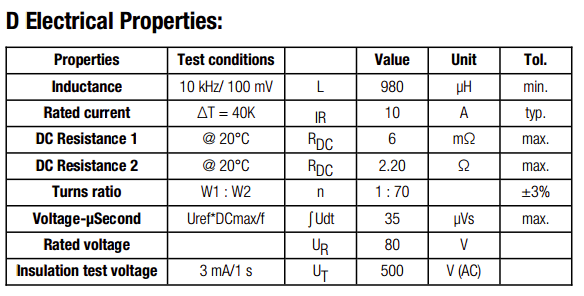
WE-CST Current Sense Transformer

Here are my (mis)understandings:

  • The Voltage-Time (Voltage-µSecond) constant somehow rates the maximum achievable voltage ramp without reaching the core saturation. Is this for the primary or secondary coil ? How does this relate to my specifications ?
  • What is the Rated Voltage ? Is this the maximum allowed voltage across the primary coil, or the maximum rated voltage across the burden resistor on the secondary ?
  • Some CTs also specify a frequency range (e.g. 40KHz to 100KHz), can I use such CTs with a much lower frequency (50Hz in my case) ? What additional parameters and bias should I take into account in this case ?
\$\endgroup\$
3
  • \$\begingroup\$ See if Wurth publish a fuller databook, with a section on what their measurements mean, test circuits, test conditions, etc. That would answer a lot of these questions. \$\endgroup\$
    – user16324
    Commented Apr 11, 2016 at 13:36
  • \$\begingroup\$ @BrianDrummond indeed, it would, but I wasn't able to find more details. Their product page only lists Eagle libraries and mechanical sizing files. \$\endgroup\$
    – strnk
    Commented Apr 11, 2016 at 13:51
  • \$\begingroup\$ @strnk: Ask them. They are very responsive and unless it falls into the domain of company secrets, they have so far been able to answer all my questions. \$\endgroup\$
    – PlasmaHH
    Commented Apr 11, 2016 at 13:53

1 Answer 1

1
\$\begingroup\$
  • Transformer core saturation is relevant to the winding in which power is applied (aka the primary). Secondary load currents (ampere turns) completely cancel with primary ampere turns due to those secondary loads. Primary magnetization current remains largely constant and it is this that causes core saturation.
  • The rated voltage for this particular CT is, I suspect, the rated voltage for the insulation - I note that the insulation voltage test being only 500V is very low for anything that might be used on power AC. I doubt that it applies to either primary or secondary voltage.
  • You can usually use CTs at lower frequencies but magnetization ampere turns will rise proportionately with falling frequency so you have to be cautious here to avoid core saturation. Going a little bit lower in frequency (but not enough to cause saturation) can mean you have to lower the burden resistor to get the same accuracy because you want the "transformed" effect of the burden onto the primary to be dominant compared to the primary reactive impedance.
\$\endgroup\$

Your Answer

By clicking “Post Your Answer”, you agree to our terms of service and acknowledge you have read our privacy policy.

Not the answer you're looking for? Browse other questions tagged or ask your own question.