I have a mains track (230VAC, 50Hz) on a custom PCB routed to multiple Solid-State Relays, and I want to measure the power going through this line.
I'm looking into Current Transformers (CTs) to sense the current on the mains track, rated at a max intensity of 2A.
I understand the principles behind the transformer itself, the burden resistor behind it, etc. I am not able to understand some of the electrical properties found in such transformers datasheets.
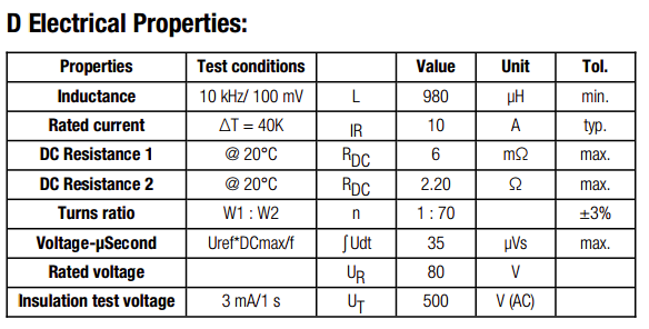
For now I focused on a WE-CST PCB-mounted CT from Würth Elektronik, whose electrical properties are presented in the following picture:

Here are my (mis)understandings:
- The Voltage-Time (Voltage-µSecond) constant somehow rates the maximum achievable voltage ramp without reaching the core saturation. Is this for the primary or secondary coil ? How does this relate to my specifications ?
- What is the Rated Voltage ? Is this the maximum allowed voltage across the primary coil, or the maximum rated voltage across the burden resistor on the secondary ?
- Some CTs also specify a frequency range (e.g. 40KHz to 100KHz), can I use such CTs with a much lower frequency (50Hz in my case) ? What additional parameters and bias should I take into account in this case ?
