-1
\$\begingroup\$

I have a NPN transistor (2N3904), I would like to be able to turn on my LED panel - 37v (don't know the amps) with my Arduino Uno, which gives output of 5v, 0.2 amps.

As far as I understood, the Arduino will be connected to the base of the NPN transistor. if I put a diode or a resistor between the Arduino and the NPN transistor's base, following the tutorials it "should" work, but I don't want to burn my Arduino down.

I don't understand, if the transistor is a 'switch', when I give electricity to the base, why is there electricity coming into the base from the collector? shouldn't it go straight to the emitter? how can I know how big of a resistance to put, between the Arduino and the base of the transistor? In addition, should do 'GRD' from Arduino go to the LED's negative terminal? Thanks

\$\endgroup\$
3
  • \$\begingroup\$ @WesleyLee not quite, the person is using the transistor under 5v, I need to use it under 37v \$\endgroup\$ Commented Apr 11, 2016 at 23:39
  • \$\begingroup\$ what are the specs to your LED Panel? its really important to know how many Amps it will draw. 37V at less than 200mA sounds strange for a LED panel.. \$\endgroup\$
    – Wesley Lee
    Commented Apr 11, 2016 at 23:42
  • \$\begingroup\$ Im almost certain your panel uses a dedicated constant current circuit, and likely has an enable pin somewhere. \$\endgroup\$
    – Passerby
    Commented Apr 12, 2016 at 0:22

1 Answer 1

1
\$\begingroup\$

IF your LED Panel draws a good bit less than 200mA (say 100mA~150mA), I'd suggest the following:

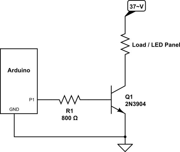
1 - As per datasheet 2n3904 hFe is minimal 30 (in practice more). In Ib = Ic/hfe, we get:

Ib = 150mA/30 = 5mA

2 - VBE max at closest match (50mA) is 0.95V, say 1V (in practice less).

So 5V - Vbe = Rb * Ib, gives ~4V = Rb * 0.005mA

Rb = 800R

3 - Schematic:

schematic

simulate this circuit – Schematic created using CircuitLab

Note that you get uncomfortably close to 2n3904 limits: Vce 40V, Current 200mA, etc..

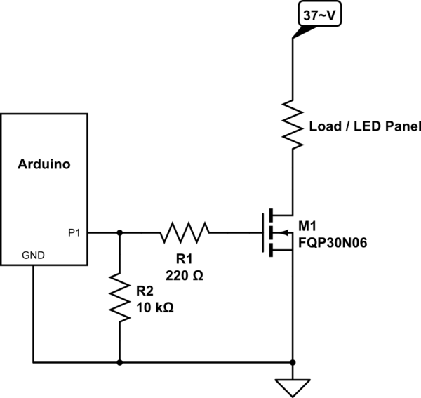
So I'd actually suggest the following:

schematic

simulate this circuit

I just used this particular mosfet because its available at Sparkfun and gives better margins (60V, 30A). You can use anything that suits your needs. (R2 optional)

\$\endgroup\$
4
  • \$\begingroup\$ Thank you very much for the answer. Quick question, what does 'Load' resistor mean? also, what if my LED panel draws more than 200mA? will that burn my Andurio? Thanks! \$\endgroup\$ Commented Apr 12, 2016 at 0:15
  • \$\begingroup\$ I used a resistor but it represents your load, the LED Panel. If it draws more than 200mA your transistor will possibly have a VERY short and unhappy life. I'd use the second option. \$\endgroup\$
    – Wesley Lee
    Commented Apr 12, 2016 at 0:18
  • \$\begingroup\$ With second option using two resistors, I can be 100% safe? \$\endgroup\$ Commented Apr 12, 2016 at 0:23
  • \$\begingroup\$ 100% safe is very hard to guarantee, I can say that it ~can~ be very durable. If you are really worried take a look into some simple techniques to protect MCU pins, such as clamp diodes, etc \$\endgroup\$
    – Wesley Lee
    Commented Apr 12, 2016 at 0:31

Not the answer you're looking for? Browse other questions tagged or ask your own question.