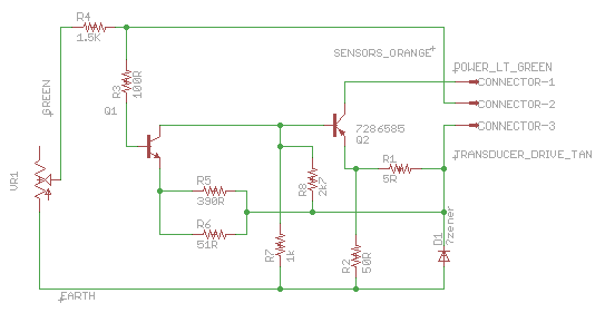
I am trying to help repair a Comfortron heating and cooling controller for a late 1960's Chevrolet Impala. The Comfortron is an early climate control system that uses a combined vacuum and electrical system to actuate flaps in the ducting and control the fan speed.
Here's the circuit as I've traced it. The Sensors input is connected to +12V through several NTC thermistors, and the Transducer Drive output drives what sounds like a thermo-electric vacuum valve that closes off (reduced vacuum) as the current through it increases; that vacuum signal controls the duct flaps and the fan speed.

The circuit is not complicated but there are a few mysteries. But I should note that Q2 is defunct so I am can't be sure it is a PNP - I don't see how the circuit would function with an NPN device. But it is in backwards, as the circuit shows. I understand that is done sometimes (eg to get low Vce(sat)) but can't work out why that would help in this case. So that is mystery number 1.
Mystery number 2 is the ID on Q2: 7286585. It is in a TO-3 case and has a Delco/GM brand on it and '6728' which I interpret as the year/week code. I can't find any useful hits on Google for that device ID but I'm not surprised - all the main components on the board have part numbers starting '7286' - two transistors and two resistors. Its as if the numbers were used specifically for this assembly.
Without a part number I will be guessing about a replacement, although judging by Delco's product lineup in the 1960s I would expect it to be a Germanium device.
Anyone care to offer an explanation for the reversed connection, or some interpretation of the part number?
Thanks :)
