1
\$\begingroup\$

I looked at a friend's guitar amplifier which wasn't working, the problem was clearly (because it fell off) a broken IC (TDA2030AC).

After replacing it, the amplifier started working again but when I was taking some measurements I made a short-circuit and burned it.

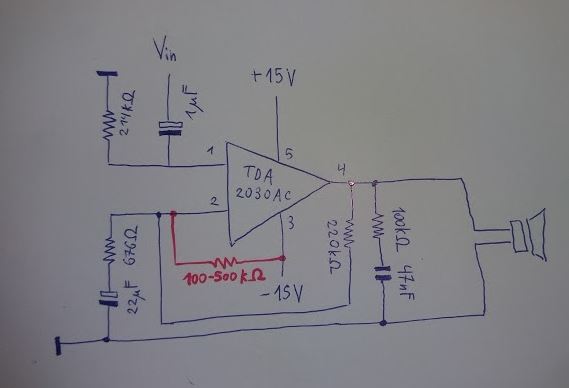
When I replaced the TDA2030AC again, the sound was very soft and distorted. I checked the datasheet and the circuit is a bit different than the recommended implementation. Some resistor and capacitor values are different, but it's a dual-supply non-inverting configuration.

The strange thing is that while making contact between pins 2 and 3 with my fingers it sounds fine. And the same occurs with a resistor between about 100 to 500 kohms (see red line in my diagram). Even if that solution works, I would like to understand what's going on and if there is likely another part of the circuit damaged.

Here is the circuit (excluding the rectifier and pre-amplifier):

enter image description here

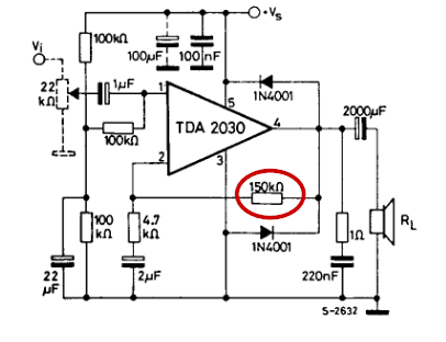
And this is the reference circuit: http://www.hestore.hu/files/TDA2030.pdf (Figure 13: typical amplifier with split power supply)

I would appreciate any clarifications, thanks.

EDIT: updated circuit diagram.

\$\endgroup\$
2
  • \$\begingroup\$ Please use the schematic button when making your post next time. It makes your schematic right-side up and fit the standard we're used to, which makes it much easier to read and answer to. \$\endgroup\$
    – Asmyldof
    Commented Apr 17, 2016 at 23:07
  • \$\begingroup\$ Ok, will do so next time. \$\endgroup\$ Commented Apr 18, 2016 at 14:41

4 Answers 4

1
\$\begingroup\$

The problem with your sketch is that there is no DC-path for pin 2. Any small bias current in or out of pin 2 will charge up the 22 uF capacitor bringing the voltage at pin 2 to either the positive or negative rail.

Since you discovered that you can fix the problem by pulling pin 2 low it seems as though the 22 uF capacitor is charging towards V+. In this case the amplifier will be running in saturation and probably only the negative half-cycles of the music(?) are being amplified.

enter image description here

Figure 1. Application note example. Note feedback resistor giving DC discharge path from the pin 2 capacitor.

The application notes shows a feedback resistor to the inverting input, pin 2. This also acts as a DC discharge for the capacitor.

\$\endgroup\$
3
  • \$\begingroup\$ Sorry, I forgot to copy that branch when cleaning up my drawing. It's present, also note that the circuit was working before so I believe there must be something else. \$\endgroup\$ Commented Apr 17, 2016 at 22:15
  • \$\begingroup\$ You were right, only half the wave is amplified. Before: i.sstatic.net/BUjJ5.jpg After: i.sstatic.net/Am8OR.jpg But I still don't understand what's wrong with the previous circuit as it has the feedback loop (I forgot to put it in the diagram only). \$\endgroup\$ Commented Apr 17, 2016 at 22:41
  • 1
    \$\begingroup\$ It is possible the feedback resistor was damaged - have you measured it? The evidence points to there being no DC path back to pin 2. \$\endgroup\$ Commented Apr 18, 2016 at 8:08
0
\$\begingroup\$

Thanks for answers, the problem was that there was a small positive DC voltage between pin 2 and ground that charged the capacitor instantly (which I'm not sure how to fix it properly, so I just added the resistor I mentioned).

But a discharge for that capacitor wasn't there before (even if it should've been) and it was working so I suppose that voltage wasn't there at the time.

Also, the discharge had to be negatively biased. When connected to ground it worked but the sound wasn't as good.

\$\endgroup\$
0
\$\begingroup\$

Yes it is all about the DC return path- the previous poster (Transistor) is right. There is no correct way to design an op-amp circuit without DC return path for the small but important polarizing currents for the inputs (nano amps in some cases). The usual practice is to link the inputs to ground indeed,using large resistors. Whenever this is not done you can assume they were making the assumption that the capacitors they will use surely have some DC leakage - in the order of the said nano amps, so all good, right? Wrong! The presence of a resistor referenced to ground is the only safe and reliable way to know that your polarizing currents for the op amp inputs are clean, and of adequate value.Guitar amps in general are ..special cases.As no-one expects hi-fi quality from them, almost everything goes with some less reputable manufacturers or even some established brands for their low-end products.So put that resistor there because it does belong there. You say that reference to ground sounds worse? please check the following - 1) soldering of the feedback resistor 2) the speaker connections. In the original schematic, there WAS an original path to ground- in2, r1, via the speaker, to ground. Maybe somehow the DC resistance of this path increased . If all connections check out (power off, unplug, caps discharged via an insulated screwdriver ...use the ohm range of the DMM ONLY after discharging caps and unplugging the appliance and all inputs!) and the speaker terminals sit ok, and are not corroded, etc maybe the chip you replaced had a higher polarizing current.. to make a long story short, there is nothing wrong with referencing the input to -V if it sounds better like that. It is audio after all.. large value resistor, small currents,all sunny.

\$\endgroup\$
0
\$\begingroup\$

Well...first thing that I came to notice in your schematic is that the resistor at pin 4 to the 47nF capacitor, it must be a resistor below 10Ω. Next thing is that, you have to replace the ic again, because the resistor between pin 2 and pin 3 is not natural, pin 2 must have 0 volts with respect to ground, when no signal is applied. We always have to use a pull down resistor from pin 1 to ground (22kΩ is fine) but pin 2 gets 0 volts from the resistor between pin 2 and pin 4, when no signal is applied. So I suggest you to bypass the capacitor at pin 2 to see if the problem is solved or not, if solved, check the sound quality if it is satisfactory or not. You can also check the voltage at pin 4 wrt ground after shorting pin 1 and pin 2 to ground, if there is any non-zero voltage then replace the IC.

\$\endgroup\$

Your Answer

By clicking “Post Your Answer”, you agree to our terms of service and acknowledge you have read our privacy policy.

Not the answer you're looking for? Browse other questions tagged or ask your own question.