1
\$\begingroup\$

I'm doing a home automation arduino / RFID project and using a 12v DC switch mode power supply to power it. This supply will be plugged in to a wall outlet. The project however will have some components inside the wall in a plastic project box. It's an electronic dog door that goes from the inside to outside of the house through a wall. I live in an area with 'critters' that I don't want coming in the house.

When I power the project with battery everything works great and I get really good read distances from the rfid tags. 13 - 18cm depending on the antenna I use.

When I power it from the DC wall supply it barely reads at all. I practically have to rub the tag against the antenna and sometimes that doesn't even get a reading. I don't have a scope to see what's really happening in my power, but it seems pretty obvious that the switch mode type supply is noisy enough to mess up the 125khz rfid signals.

When I connect my circuit's GND to the 3rd prong ground on the wall socket my read ranges go back up almost as good as with the battery. Maybe 1 - 2cm less.

I have a 2-fold question:

Q1: My house was built in the USA in 2015 and has 3 prog wires everywhere. That should mean that all my ground wires are true ground, correct? They shouldn't be connected to the AC neutral wire? Are these are connected to earth?

Q2: My project will be installed in a wall in my house and there is a nearby outlet. Can I / is it safe to run a ground wire from that outlet to the project box (inside the wall) to ground my project circuit? OR is there another better way to properly ground the project.

[Update 2 - What I did] I don't feel that my question about safe grounding was answered. Everyone tried to solve a problem in my circuit, which I had already solved by grounding. I couldn't make power cables shorter but I did twist them as suggested. I added a grounding wire and attached it to some sheet metal that goes around the outside of the house. My read range is acceptable.

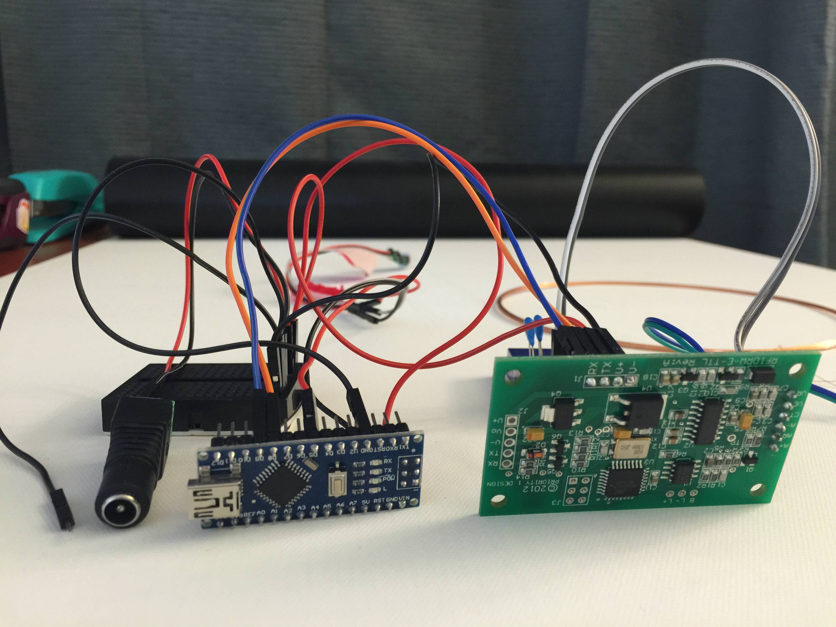
[Update 1] As requested here is a photo of the project on breadboards:

Arduino RFID Project

Vcc and Gnd from the power adaptor go to the black breadboard and are distributed to the Arduino Nano and the reader module. The black jumper wire on the left is the one I connect to wall ground to improve read distance. The orange/blue jumpers are RX/TX to the reader. The grey jumper cables go to 2 antenna tuning capacitors in the back. This is per the rfid reader board's manufacturers instructions. Green/Blue go to the antenna. There is also a PIR motion sensor in the back but it isn't affecting this issue as removing it makes no difference.

Also to clarify something. I can completely remove the arduino and only connect power to the rfid reader board. Isolate that one component. By attaching an LED there I can see when it reads a tag. Same results are happening even when that board is used alone: battery power = good read ranges, dc supply = bad ranges or no reads at all, dc supply with gnd connected to house ground = good read ranges.

\$\endgroup\$
17
  • \$\begingroup\$ Have you tried different power supplies? Maybe the particular one you are using is of bad quality and hence causing the issue. If another good quality wall adapter works, you can call it a day. Usually SMPS ICs have frequency between 60 kHz to 120 kHz so there might be a possibility but a well made SMPS should work. \$\endgroup\$ Commented Apr 23, 2016 at 7:02
  • \$\begingroup\$ I've tried 4 or 5 different ones, different manufacturers, some that I bought specifically to power arduino projects, and some that I have around the house like 12v hard drive supplies. \$\endgroup\$
    – badweasel
    Commented Apr 23, 2016 at 7:04
  • \$\begingroup\$ One more suggestion - Try adding big filter cap - 16V 1000uF or so at the entry point of wall adapter and 0.1 uF decoupling capacitor as well close to the micro controller. If you are resourceful, try making a PI filter (2 caps 1 inductor). See if it helps. \$\endgroup\$ Commented Apr 23, 2016 at 7:11
  • \$\begingroup\$ Your talking on the DC side of the power adaptor? I'm not an EE I'm a dangerous coder with a soldering iron, which is why I'm here asking. So I don't know where you mean that the cap should go - between what and what? And "close to the micro controller" - everything is close to it. It goes DC power plug and then 4 inches of wire and then the arduino. \$\endgroup\$
    – badweasel
    Commented Apr 23, 2016 at 7:15
  • \$\begingroup\$ Are you using proper arduino board? Or you made one yourself using Atmega328 IC on a PCB? Can you please share an image of the setup? \$\endgroup\$ Commented Apr 23, 2016 at 7:22

2 Answers 2

1
\$\begingroup\$

Firstly, Looking at your photo, you need short cables, and on the main power cables, twist them with their respective 0v/earths, for good practice, even on a prototype.

For a test see if you can get your hands on a ferrite core that attenuates at your switching power supply's frequency around 125kHz. Try robbing one from an old switching power supply (smpsu) . They look like a donut shape bulge on the output or input to a SMPSU.

Place ferrites over all the output/or/ and input power supply cables, including gnd, from the switch mode, then see if this helps.

If this does help then it's common mode interference coming from the switching power supply.

You can also try grabbing all the cables in your hand, making sure they are insulated and not electrically connected, and try and earth yourself. It sounds silly but you are a capacitor to gnd for high frequency common mode signals! This will tell you it's common mode.

But mainly in response to your question, I would strongly recommend grounding to metal pipework, It's probably safer, and legal, to earth to your pipework, rather than your house's electrical system . All mettle pipework should be earthed.

You need to find the main path of interference, these things can be very tricky to sort out and one can go round in circles, but try the earthing to pipework, with short multi core cable, first.

\$\endgroup\$
1
  • \$\begingroup\$ Thanks. I accepted the answer for the suggestion to ground to metal pipework. I grounded to a metal stripping at ground level that goes around the bottom of the house. Since this is an electronic dog door project there is a hole in the wall that goes clear outside and without the dog door installed I have easy access to that metal strip. I'll post a photo of it. \$\endgroup\$
    – badweasel
    Commented Apr 26, 2016 at 20:38
1
\$\begingroup\$

Firstly, the neutral is usually connected to the earth but ONLY at the fuse box (that connection is what keeps the neutral neutral). Running just the ground from an outlet is no big deal, I used to work for a company where they grounded their EMC test bench that way. It does sound like you've got a noisy power brick though, a bit of low esr capacitance on the board (a few uF of anything other than an electrolytic) and a shield around just the power supply should probably do it.

\$\endgroup\$
1
  • \$\begingroup\$ When I tested my circuit I was using a specific extension cord. Logistically I needed to get power to where I did the testing. Installed the power adaptor is directly in the wall. Technically I don't know if it's also dirty power directly from the wall. Someday I'll buy a scope and check these things out. But meanwhile the install is working as is. I could use a little more read range but working on that on the antenna end. Thanks again. \$\endgroup\$
    – badweasel
    Commented Apr 27, 2016 at 3:06

Your Answer

By clicking “Post Your Answer”, you agree to our terms of service and acknowledge you have read our privacy policy.

Not the answer you're looking for? Browse other questions tagged or ask your own question.