1
\$\begingroup\$

My fourth electronics project ever. The most challenging yet.

I've wired up this project (Project 4 - Short Circuits project kit Jaycar Electronics). After much research, it doesn't do what I expected. I complete the circuit by touching the two probe wires together and the LED flashes - so far so good.

I then disconnected the wire running from the emitter to the 100k resistor and connected the two probe wires again. The LED still flashed. I expected it not to flash because the base current can't flow through a circuit (out of the base) due to the fact the circuit was broken by me disconnecting the wire.

My expectation was that no current can flow between the collector and the emitter until a base current was supplied. Perhaps the calculation of the impedance was understated and a current would flow from the collector through to the emitter anyway because the current is simply to big for the transistor to resist, base current applied or not!
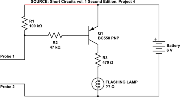
schematic

simulate this circuit – Schematic created using CircuitLab

I think I'm missing something quite fundamental here. I'm not experienced enough in electronics to accuse a textbook of being incorrect.

\$\endgroup\$
4
  • \$\begingroup\$ Looks as if the battery is reversed... \$\endgroup\$
    – Nedd
    Commented Apr 24, 2016 at 5:43
  • \$\begingroup\$ Could you redraw the circuit the conventional way please, +ve at the top, -ve at the bottom. That will increase the number of people (to at least include me) that will think about an answer. \$\endgroup\$
    – Neil_UK
    Commented Apr 24, 2016 at 5:48
  • \$\begingroup\$ Seems to be the Short Circuit (Continuity) Tester from Jaycar: jaycar.us/Kits%2C-Science-%26-Learning/Educational-Learning/… \$\endgroup\$
    – Nedd
    Commented Apr 24, 2016 at 6:05
  • \$\begingroup\$ I've redrawn and corrected your circuit diagram to match that shown in the Jaycar project. \$\endgroup\$
    – Nedd
    Commented Apr 24, 2016 at 7:52

2 Answers 2

2
\$\begingroup\$

Assuming battery + is on the transistor/R1 connection, and battery - to the lamp/Probe 2 connection:

By disconnecting the wire going to the 100K you are only removing the part of the circuit that tries to ensure the transistor stays off when it should. The 100K makes the circuit a bit less sensitive so that only a somewhat lower resistance short (between the probes) turns on the lamp (or LED). With out the 100K connection there is a chance that the lamp turns on slightly if you just short the probes with your hands.

But even with out that connection to the 100K, shorting probe 1 to probe 2 will still pull current through the emitter/base connection of the transistor, (with the path being from the battery, to emitter, to base, through R2, probe 1, probe2, and back to the battery.) This turns on the emitter to collector path, turning on the lamp.

\$\endgroup\$
1
  • \$\begingroup\$ @Nimbocrux, does this satisfy your working idea of how the circuit operates? \$\endgroup\$
    – Nedd
    Commented Apr 25, 2016 at 7:35
2
\$\begingroup\$

You are misunderstanding the purpose of R1. You seem to think it has something to do with supplying power to the probes in order to make the light turn on. Actually, R1's purpose is to make the light go off when the probes are not touching each other.

When the probes are touched together, current flows from the battery (+) through the emitter to the base, and then through R2 to the (-) (what would ordinarily be ground). This base-emitter current biases the transistor on which lights the light on behalf of the resulting emitter-collector current.

R1's job, then, is to try to hold the base at the same voltage as the emitter, so the transistor (and light) will stay off when the probes don't touch.

\$\endgroup\$

Your Answer

By clicking “Post Your Answer”, you agree to our terms of service and acknowledge you have read our privacy policy.

Not the answer you're looking for? Browse other questions tagged or ask your own question.