0
\$\begingroup\$

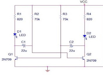
I have built a simple circuit with two diodes that light up intermittently. It requires 9V DC voltage to run.

I don't have a DC source at home, and would like to avoid buying 9V batteries repeatedly to power my future projects, as portability is not necessary.

I however have a battery charger (wall adapter with battery slots), which can also recharge 9V batteries. I thought that battery powered devices are often able to run plugged in without the battery, so this should be the case here, too.

So I tried to connect the wires where the 9V battery to-be-recharged would normally fit, but it's not working as expected: D2 stays on indefinitely, while D1 flashes for a brief moment about once a second.

Note: The charger has a led indicating whether the battery in the respective compartment is charging. It does NOT light up when the circuit is connected.

Normally, they are supposed to flash intermittently, about one second each.

(The circuit works correctly, tested with a 9V alkaline battery).

I don't understand why this happens, and would greatly appreciate some help!

enter image description here

\$\endgroup\$
3
  • \$\begingroup\$ Try putting a 100uF capacitor between the Vcc and ground (observing correct polarity) and re-test. \$\endgroup\$ Commented Apr 27, 2016 at 12:30
  • \$\begingroup\$ Which charger do you use? \$\endgroup\$
    – Christian
    Commented Apr 27, 2016 at 12:30
  • \$\begingroup\$ This is the charger: batterylogic.co.uk/docs/Manual_X-Press_150_UK2.pdf Unfortunately, I don't have spare components at home (I plan to buy a breadboard and some components in the future). I will try to go back to the university laboratory and install some new components on the board as needed. Thank you for your interest! \$\endgroup\$ Commented Apr 27, 2016 at 12:47

4 Answers 4

3
\$\begingroup\$

Your circuit will work at 5V too. It may flash a little faster and the LEDs may not be quite as bright but both those issues can be adjusted by tweaking the values of the 75K and 820 ohm resistors accordingly.

I mention this because of the plentiful supply of cheap 5V USB device chargers around these days. One of these may be a good alternative to powering your circuit.

\$\endgroup\$
2
  • \$\begingroup\$ Thanks! Found an old 5V phone charger and it works like a charm! \$\endgroup\$ Commented Apr 27, 2016 at 13:47
  • \$\begingroup\$ Glad it worked out for you. :^) \$\endgroup\$ Commented Apr 27, 2016 at 13:55
3
\$\begingroup\$

After your edit to mention that it works correctly on a 9V battery, I expect the problem is that your 9v charger has some "smarts" and only charges when it "thinks" it sees a 9V battery attached.

The charger could be checking a few things to see if it should start the charge cycle.

  1. Existing voltage - the charger checks to see if there is a partially charged battery attached and only starts charging if there's some voltage coming in from the battery connector. A "dead" battery isn't really zero volts (it would be 6 or 7V for a 9V battery.)
  2. Check for a load, and shut off if there's no load attached - the charger thinks there's no battery to be charged and shuts off.
  3. Stop the charge cycle if the load is too low - it thinks the battery is charged.

Number 3 is the most likely, follow by number 2.


Thought of a number 4:

The charger is putting out pulsating DC and keeps resetting your circuit. In this case, the capacitor that @JIm Dearden mentions would help.

\$\endgroup\$
3
\$\begingroup\$

As already stated, a modern 'smart' battery charger won´t make a good power supply. A smoothing capacitor across the output may work, but maybe you should consider some other options, especially for the future:

You could:

1) Buy a couple of PP9 rechargable batteries to use with your projects - and so make proper/full use of your charger.

2) Buy a 'wall-wart' power supply - they are quite cheap and most have multiple voltage outputs so could be used for a variety of projects.

Or better:

3) Build a small, variable, power supply. There are plenty of simple circuits out there (eg based around the LM317). If you are going to experiment with electronics, a variable power supply is pretty much essential.

\$\endgroup\$
4
  • 1
    \$\begingroup\$ This doesn't answer the question. \$\endgroup\$
    – Rob
    Commented Apr 27, 2016 at 13:16
  • \$\begingroup\$ True, but it certainly isn't a bad answer. \$\endgroup\$
    – rdtsc
    Commented Apr 27, 2016 at 13:42
  • \$\begingroup\$ @Rob: Ok, edited my answer to be more of an answer! \$\endgroup\$
    – F. Bloggs
    Commented Apr 27, 2016 at 13:47
  • \$\begingroup\$ @rdtsc Not to belabor the point or sound like I'm picking on him but if it doesn't answer the question then it's not an answer at all. \$\endgroup\$
    – Rob
    Commented Apr 27, 2016 at 13:50
-1
\$\begingroup\$

Using Battery Charger is not good way, since the charger only source 10% -20% of current requirement to charge the battery.

for example if the battery is of 3V,100mAh then using constant current charging method which normally this kind of battery charger use source only 10mA of current to charge the battery.

Also battery charger considers no-load condition because directly battery is needed to charge. Now you have your circuit powered directly with this charger which would only source 10% of current rating to your circuit which might be insufficient for 2-leds & 2-Transistors to work(since its now a load condition)

hence i would suggest calculate your total current requirement and also check the rating of battery charger, it should be higher then your current req.

Do let me know for any further issue.

\$\endgroup\$
1
  • 1
    \$\begingroup\$ Powering 2 LEDs is far below any 'normal' charging current for a 9V batt. charger, so your answer has virtually nothing to do with the question. \$\endgroup\$ Commented Apr 27, 2016 at 13:07

Your Answer

By clicking “Post Your Answer”, you agree to our terms of service and acknowledge you have read our privacy policy.

Not the answer you're looking for? Browse other questions tagged or ask your own question.