0
\$\begingroup\$

I have a problem where I am passing pulses received from a photo-diode into a high pass RC filter. Circuit shown below.

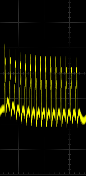
The pulses are being received at 25Khz. Before the filter, the pulses are measured as expected. After the filter, the signal gets shifted as shown below and only seems to stabilize after around the 10th pulse. I assume that this is due to the RC time constant of the HPF.

This is a problem as I then amplify the signals after by an op-amp with a 0v cut off so I am then left with an inaccurate decaying signal.

The values of the capacitor and resistor in the HPF are selected to have a cut-off frequency of around 1500Hz.

Would anyone have a solution to this problem or some recommendations? It would be greatly appreciated. Can I change the filter in anyways to stop this signal shift? Thanks

enter image description here

The signal-not a great picture but the shift down can be seen. enter image description here
\$\endgroup\$
8
  • \$\begingroup\$ What are you ultimately trying to do with the pulses. Don't mention high pass filters or op-amps in your response to this question. \$\endgroup\$
    – Andy aka
    Commented Apr 28, 2016 at 14:52
  • \$\begingroup\$ I wish to amplify them and then send them to an ADC, so I need the exact real amplitude of each pulse \$\endgroup\$ Commented Apr 28, 2016 at 14:54
  • \$\begingroup\$ Since you are going to amplify, might aswell incorporate the filter in the gain stage using a single op-amp. Op-amp filters are more flexible with what you can obtain. If you opt for this option find a filter design tool online. \$\endgroup\$
    – Adam Z
    Commented Apr 28, 2016 at 14:59
  • \$\begingroup\$ As it is now, the output of the HPF is going into an opamp. What do you mean to incorporate it into the gain stage? thanks \$\endgroup\$ Commented Apr 28, 2016 at 15:05
  • 1
    \$\begingroup\$ So what you are doing here is known as a passive filter. You can instead use an active filter. An active filter gives you more flexibility as what to set the filter parameters. When you design an active filter you can set it to have a certain gain. Therefore your signal can be amplified and filtered with a single op-amp. You can find tools online to do the filter design for you given your required parameters. This is the one I use Texas filter \$\endgroup\$
    – Adam Z
    Commented Apr 28, 2016 at 15:20

1 Answer 1

2
\$\begingroup\$

I need the exact real amplitude of each pulse

Then differentiate the signal more thoroughly like this: -

enter image description here

The idea behind this is that you use a "strong" high pass filter that is high enough to decay the DC content within one pulse.

Then measure the peak of the red signal. You can measure it at several points of course and translate each reading to a projected peak reading. You could even low-pass filter in software to recover the shape of the original signal and hence deduce the amplitude.

Try using a simulator also.

\$\endgroup\$
8
  • \$\begingroup\$ I am using PartSim. I would still need the original pulse length for the sample and hold of the ADC \$\endgroup\$ Commented Apr 28, 2016 at 15:21
  • 2
    \$\begingroup\$ Use a faster device or do some calcs as I suggested to determine what the peak is. I cannot hope to know what circuitry you fully have at your disposal so please don't make this an endless set of moving goalposts. \$\endgroup\$
    – Andy aka
    Commented Apr 28, 2016 at 16:50
  • \$\begingroup\$ Andy, when using a strong high pass filter and the output is as above with spiky pulses, should passing this again through a low pass filter after the amplification stage flatten the pulses, but is that then just defeating the purpose? Will that then re-introduce the low frequency content from the original signal or will the DC and low frequency content already have been blocked out? It's difficult to see by simulation. The problem of course that i'm having now is that with the red signal above, the ADC isn't getting time to see the full amplitude. Thanks again \$\endgroup\$ Commented May 3, 2016 at 13:42
  • \$\begingroup\$ Use an op-amp integrator which has its capacitor discharged when the output spike is negative. This should work because you are resetting any DC build each cycle. \$\endgroup\$
    – Andy aka
    Commented May 3, 2016 at 13:47
  • \$\begingroup\$ I will try that. Do you think it's better to put the integrator before the op-amp used for amplification or after? If placed after, the signal going into the integrator will only have positive spikes. Thanks \$\endgroup\$ Commented May 3, 2016 at 15:35

Your Answer

By clicking “Post Your Answer”, you agree to our terms of service and acknowledge you have read our privacy policy.

Not the answer you're looking for? Browse other questions tagged or ask your own question.