I tried with some configurations in which 16+16 MOSFETs of 240 A each (really they are case limited to 80-90 A because of source terminal, but I doubled this termminal with a very thick copper wire for each of them) were configured in a very symetrical arrangement, 16 MOSFETS in transistor position and 16 in synchronous rectifier configuration, and they still seems to fail at some points and I can't figure out how to avoid failure.
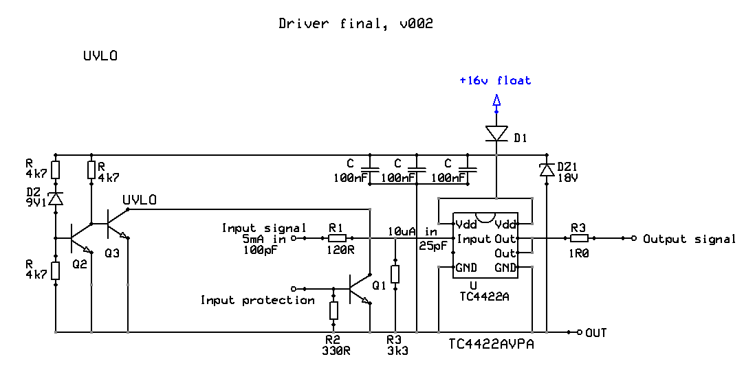
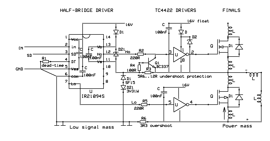
They were attached all with a IR21094S as driver, and each 2 transistors were driven by a MOSFET totem-pole TC4422 driver.
The motor is a 10 kW DC compound motor, that is 200 A nominal and takes probably 1600 A at start. The inductance seems to be 50 μH, the rising current speed in pulses is 1 A/µs at 50 V. Frequency chosen is 1 kHz, PWM buck with synchronous rectification configuration.
I can't figure out why, even though the circuit was carefully made, with 4 modules symetrically supplied and with separate output conductors up to the motor, and with independent snubbers, and with a motor snubber, the transistors still fail.
The circuit seems to work fine but, after some time, like tens of minutes (temperatures are normal, some 45°C) usually at accelerations, the synchronous diodes fail, followed by all the transistors.
I initially tried to sense current on the MOSFETs using a small MOSFET in parallel (drain-drain, gate/gate through a Zener, source of small MOSFET to a 22 Ω resistor and after to a voltage amplifier to activate a fast-shutdown protection circuit), but because of faster commutation time the small MOSFET entered always before the main transistor, disturbing the protection circuit and making it unusable.
There is no shot-through, I used a 2 μs gap through driver. I only suspect asymmetry in the parasitic inductances. How many MOSFETs did you guys parallel succesfully and in what conditions?
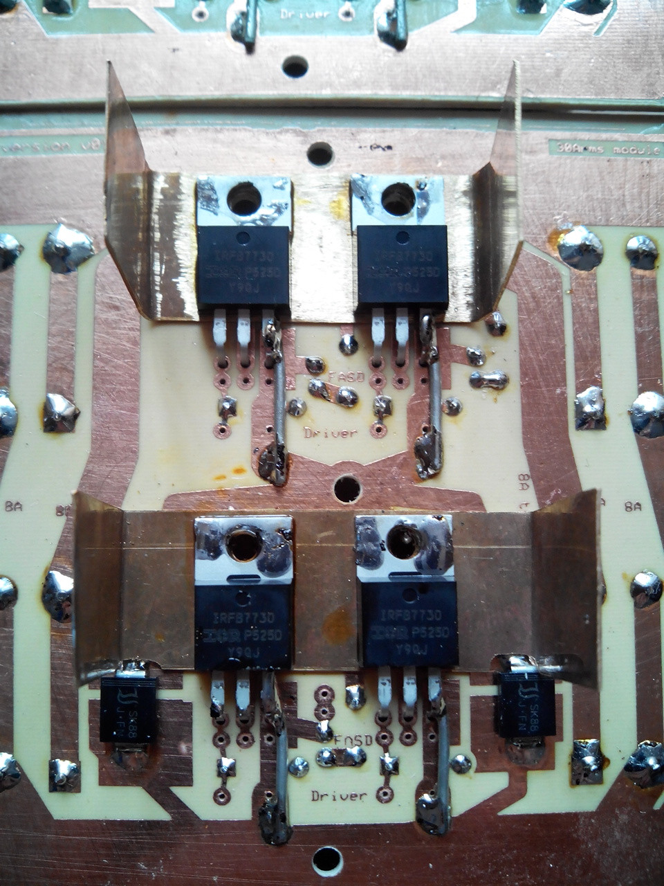
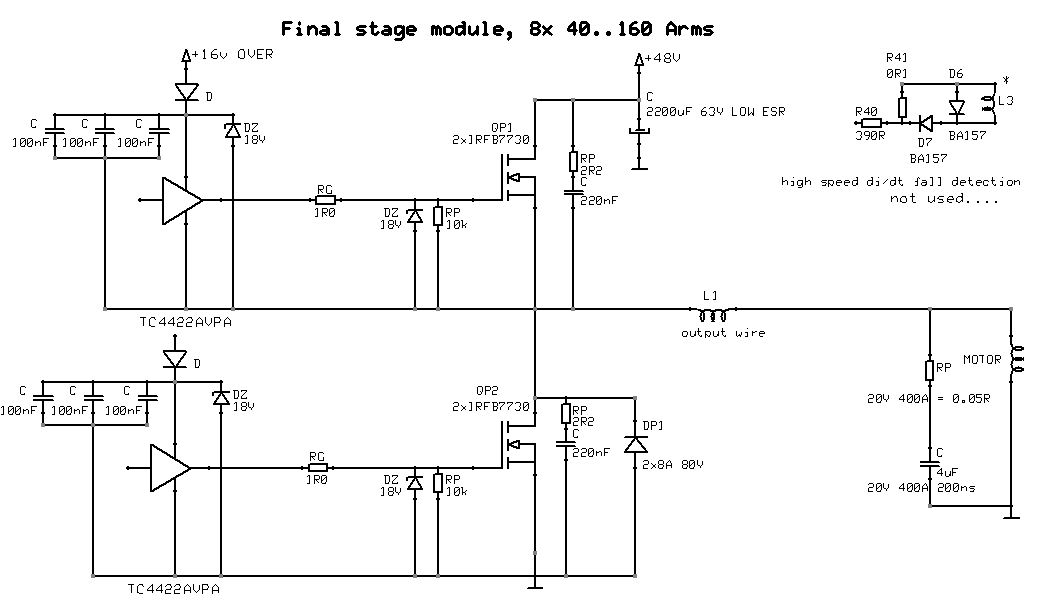
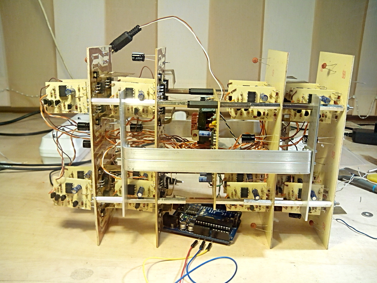
This is one of the 8 power modules:
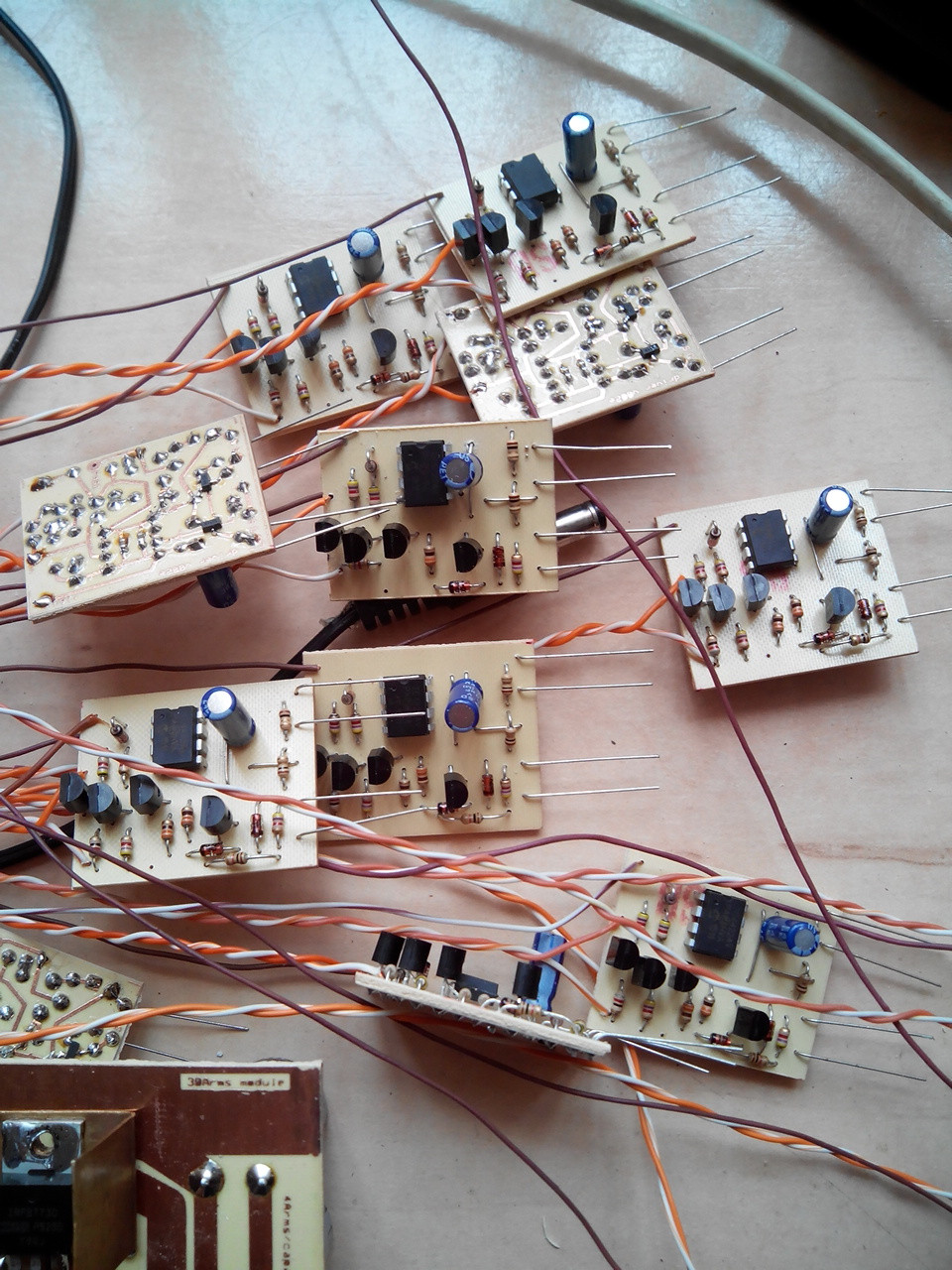
This is the driver for two transistors, MOS or SYNCH MOS, identical:
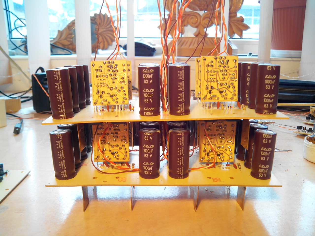
Here is all the assembly, simplified, but detailed in the main half-bridge driver section:
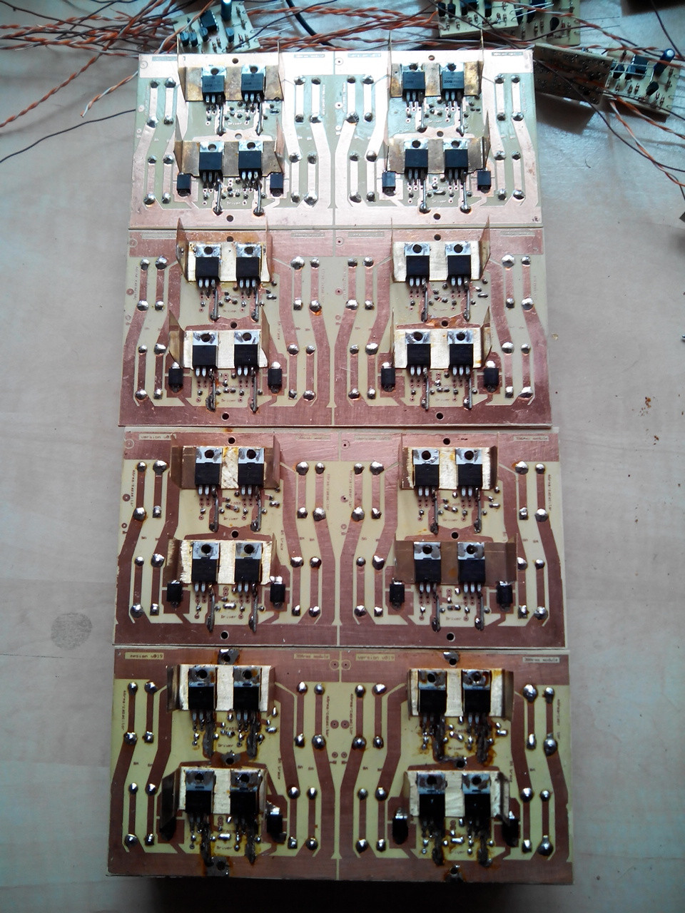
All stacks, without capacitors:
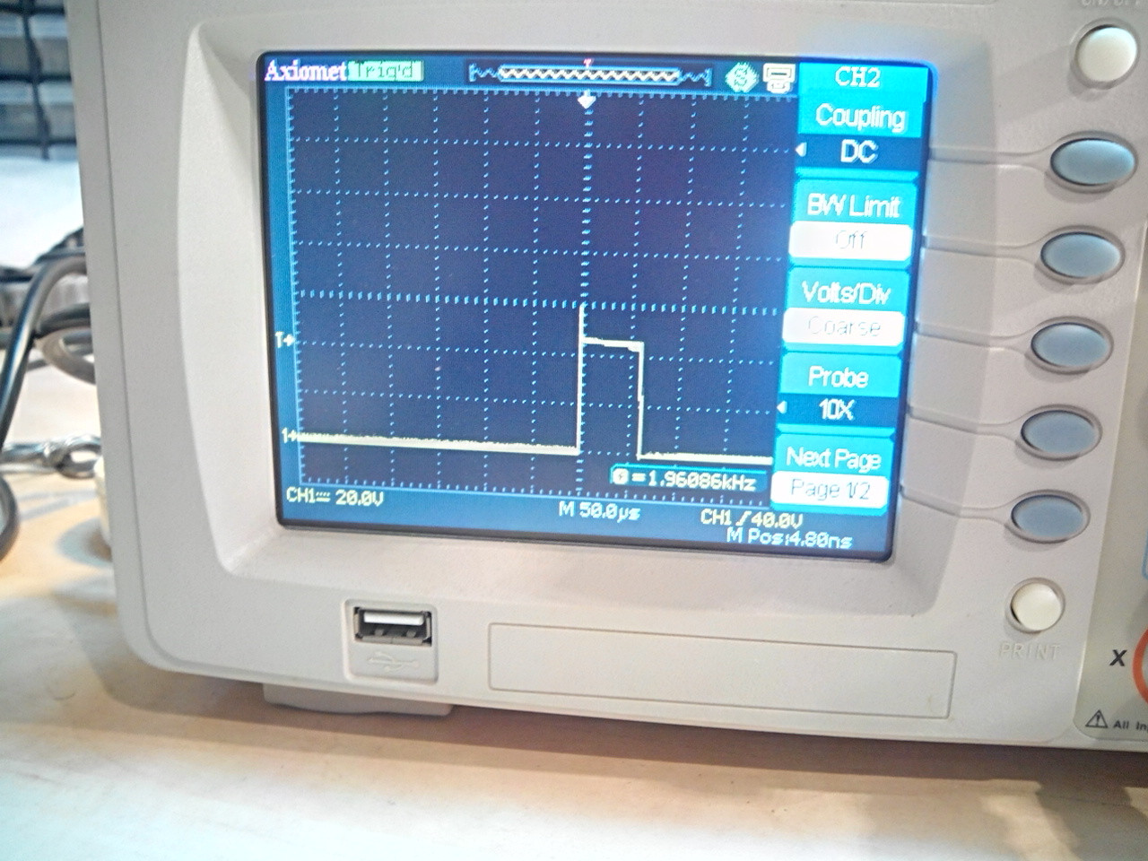
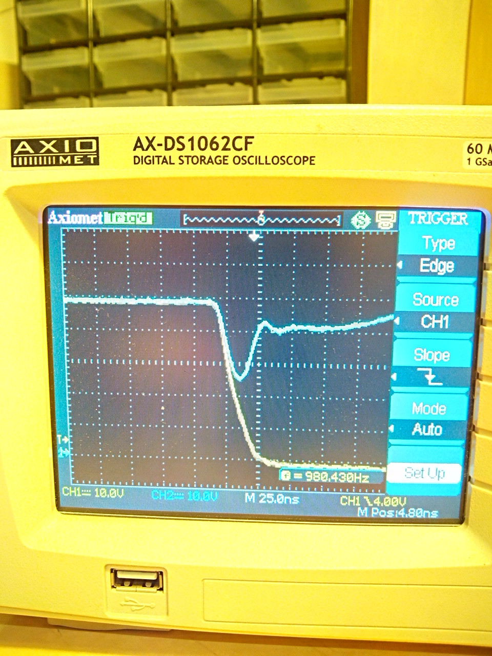
Falling edge, output yellow, 48 V supply blue. Supply is sustained only by some sporadically distributed 100 μF and 100 nF ceramic capacitors, to avoid MOSFET burns by initial tests mishandling.
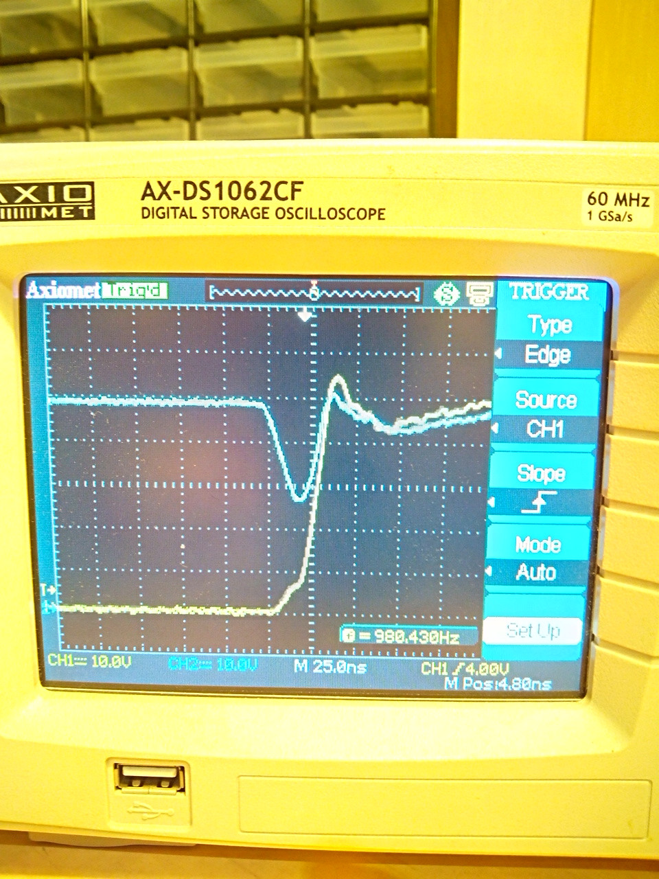
Rising edge; you can see the overshoot is very small, only 5 V. Transistors have a 75 V rating

