0
\$\begingroup\$

3 way level shifter

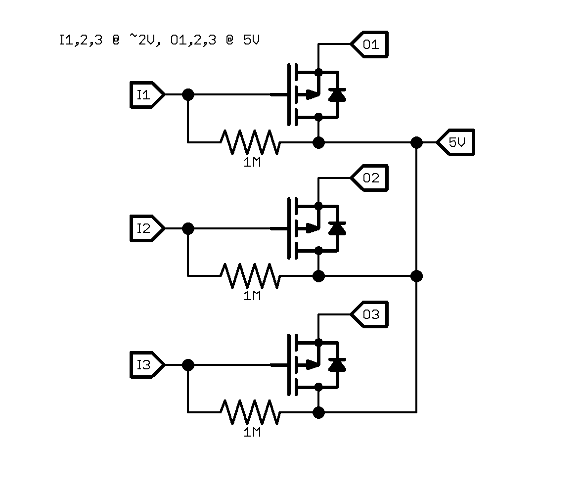
I need to change 3 signals (I1,2,3) which will be at around 2V to get shifted to 5V (in one direction only to O1,2,3). This schematic should do the job, but does anyone know if:

a) there's a better way to do it?

b) there's an IC which does this in a single package?

The way it works is: to set an output (O1-3) to low, the pin connected to the corresponding input (I1-3) should be pulled to anything below about 3.5V, to set it high, the pin should be floated. It works on a breadboard and seems to be the simplest way I can think of to do it.

The power consumption will be very small, a few milliamps. Oh, and these are P style MOSFETS.

\$\endgroup\$

1 Answer 1

1
\$\begingroup\$

Sure, there are myriads of level-shifter ICs. Here is one that meets your needs and is fairly cheap. There is only one unidirectional channel so you'd need three for your example.

This one will do four channels in one IC and is a little cheaper per channel.

Since these parts may be obsolete someday and to keep this answer (ahem) "timeless," here is the procedure to find this in general: Go to DigiKey (or any vendor, but I like DigiKey's filtering), search "level shifter" and then start filtering by "unidirectional" and where the Vin supply (2V) falls between the range, and where the Vout supply (5V) falls between.

One last thought, I wouldn't use the circuit that you've breadboarded because there is no real path for a logic LOW. It may be working for you, but will depend on the load your driving having internal losses that eventually pull the load low. In other words, it should be a floating output but it goes low, meaning high impedance and noise sensitive. Use a level-shifter IC like I've pointed you to here and actually drive the signal low to avoid other problems down the line due to noise.

\$\endgroup\$
3
  • \$\begingroup\$ Thanks, that looks like it will be perfect (although reflowing a TSSOP-14 might be a challenge!). On your comment regarding the lack of a logic low path, I'm not sure I understand - if I want a low output, I float the input and then the gate minus source = 0v, which switches off the FET, right? If I drive the input at all (0v, 2v, anything up to about 3.5v), then the gate minus source > 1.5v and it switches on the FET. There's nothing else connected to any of the lines (inputs come from PIC IO ports, outputs go into input pins on an LED driver). \$\endgroup\$ Commented May 5, 2016 at 17:30
  • \$\begingroup\$ I don't dispute that the PFET is turned off. But that is not the same as driving your output LOW... there is not even a ground in your circuit! :) Let's say you hooked O3 to charge/discharge a capacitor. I'm saying if it goes LOW like you're seeing on your breadboard, it's just due to internal parasitic resistances to ground. If you bought an expensive capacitor, your output would float high a long time. p.s. TSSOP is not bad with a little practice. You can do it. \$\endgroup\$ Commented May 5, 2016 at 17:34
  • \$\begingroup\$ Ah, I see, so I need a puil-down on the output, and the ready made IC provides that. Nice one, thanks. \$\endgroup\$ Commented May 5, 2016 at 18:55

Your Answer

By clicking “Post Your Answer”, you agree to our terms of service and acknowledge you have read our privacy policy.

Not the answer you're looking for? Browse other questions tagged or ask your own question.