0
\$\begingroup\$

In a previous question, I asked how to amplify a CT sensor, essentially a small transformer that induces a voltage proportional to the current in the primary circuit. The solution has one leg attached to a voltage in the middle (2.5V for a 5V source):
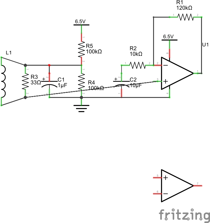
op amp for CT sensor

enter image description here Can I connect multiple CT circuits sharing the same base voltage or will that create a lot of noise and/or affect each other? In other words, if I want to create 8 of these, can I share the voltage divider among all 8 circuits? Would making C1 larger help? Further, if two CT sensors were observing circuits from different phases, would that be a problem?

My intuitive sense is that a 100uF capacitor and many CT sensors sharing the same base voltage should be more stable rather than less, is that wrong?

\$\endgroup\$
2
  • \$\begingroup\$ Your op-amp circuit has no parameters to work with except Vcc. What frequency range is this working with? Are you sure R3 is the correct load for the CT? What is this circuits tracking range in term of L1 primary amps? Square wave or sine wave? \$\endgroup\$
    – user105652
    Commented May 16, 2016 at 3:30
  • \$\begingroup\$ The first CT sensor I worked with had a burden resistor of 33 ohms. The current set are 10 ohms. This is 60 Hz AC power, the CT sensors yield 20mV on a 20A circuit at full load. \$\endgroup\$
    – Dov
    Commented May 16, 2016 at 5:04

2 Answers 2

3
\$\begingroup\$

Yes, you can probably share the divider. The only currents it sees are capacitively coupled and currents that flow through the op-amp input. They will cause small errors, but probably not significant to you.

I would suggest reducing the divider resistors to 5K or 10K each and increasing the capacitor to 100uF.

\$\endgroup\$
2
  • \$\begingroup\$ You're saying to reduce the divider resistors so there is more current keeping the voltage stable? Any advantage to an even bigger capacitor? \$\endgroup\$
    – Dov
    Commented May 16, 2016 at 5:02
  • 1
    \$\begingroup\$ The lower resistors also help with cap leakage and keep it from taking too long to stabilize. I don't think a larger cap will help much, but you might want to parallel it with 100n ceramic to deal with higher frequencies. \$\endgroup\$ Commented May 16, 2016 at 5:05
1
\$\begingroup\$

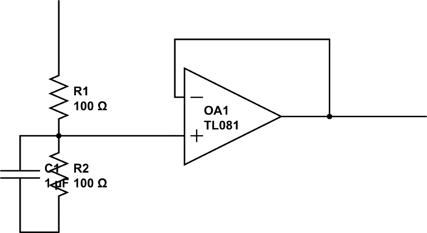
You can add a buffer.

schematic

simulate this circuit – Schematic created using CircuitLab

\$\endgroup\$

Your Answer

By clicking “Post Your Answer”, you agree to our terms of service and acknowledge you have read our privacy policy.

Not the answer you're looking for? Browse other questions tagged or ask your own question.