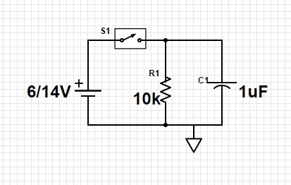
The discharge time of a capacitor in a RC - circuit should be an exponential function with a time constant of RC. This is quite well established model and should be quite accurate under reasonable circumstances.
In your setup it is important to know how you define fall-time. If you use a fixed voltage level, for example 0,5V as the end point for the discharge process it will take different amount time for voltages in range of 6 -18V. However I assume you use a level which corresponds to a percentage of the charging voltage.
Next step is identifying your voltage source. If you use a variable power supply you must look into the specifications, typically you would need a circuit for it or a good data sheet. One thing to consider is that many of these devices have a capacitance on the output, anywhere in the range of 1muF to 470muF which is parallel to the capacitor under test. But that one has same value regardless of voltage.
If you are using batteries you will definitely be in trouble – depending on the type and size their resistance varies, but for a alkaline AA 1,5V you can expect something like 0,15 Ohm at room temperature.
Generally speaking you can calculate the internal resistance of your voltage source by measuring the voltage at no load and at load Rl. However this will be accurate only for unregulated voltage sources.
Rint = (Vnl/Vfl - 1)Rl
However to determine exactly what causes the discharge time to vary full information needs to be provided for your voltage source.
A simple solution would be to simply remove it from the circuit at the start of the discharge process. But that was not what you were asking about.

