1
\$\begingroup\$

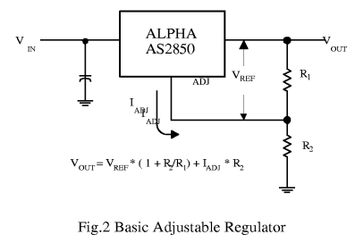
I'm working with an adjustable voltage regulator and am having a hard time understanding my equation for determining resistor values.

Datasheet: http://www.chinaeds.com/zl/20103612559506780_AS2850YU-X,AS2850YT-X,AS2850AUPDF.pdf

Figure 2

I'm able to get ~5V (my goal) on Vout when using the following values:

  • Vin = 12V
  • R1 = 22K
  • R2 = 1.47K (1K and 470 in series)

As soon as I put a load on Vout it drops to ~3.7V

What am I doing wrong?

Edit: turns out I had multiple regulators that were bad. Once I found a good one everything works as expected (with the proper resistance values).

\$\endgroup\$
9
  • \$\begingroup\$ The input voltage has to be more than 6.2V at the troughs of any ripple to get a solid 5V out (preferably somewhat more than that). It is probably dropping under the load. \$\endgroup\$ Commented May 20, 2016 at 14:43
  • \$\begingroup\$ My power supply (12V 1A) works perfectly fine with a fixed output voltage regulator. (datasheet.octopart.com/…) TO-220 package. I just need a tiny bit more than the 1.5A it can handle. \$\endgroup\$ Commented May 20, 2016 at 14:46
  • \$\begingroup\$ You're pulling 1.5A out of the this regulator and your 1A power supply? Hmmmm ... do you have a heat sink on your regulator? have you checked you 12V in at 1.5A? \$\endgroup\$ Commented May 20, 2016 at 14:49
  • \$\begingroup\$ @MichaelAmbrose: so you are pulling more than 1.5A through a regulator rated for 1.5A from a PSU rated at 1A? \$\endgroup\$
    – PlasmaHH
    Commented May 20, 2016 at 14:49
  • \$\begingroup\$ Heatsink: yes. More than 1.5: trying to run a Raspberry Pi so only at peaks. That's why I got a different regulator. The final install will be using a 12V 3A adapter. The fact that I can get 5V from the fixed regulator makes me think I'm doing something wrong with my calculation. ** To clarify**: everything works perfectly fine with the 12V 1A PSU and 1.5A regulator. I just can't use it as my final install. \$\endgroup\$ Commented May 20, 2016 at 14:54

3 Answers 3

1
\$\begingroup\$

The current \$I_{ADJ}\$ is very small and constant. Therefore its contribution to the overall output voltage is very small and can generally be ignored.

\$I_{ADJ}\$ is 40-80\$\mu\$A.

So how are you getting 5V? Calc gives:

\$ V_{OUT} = V_{REF} \times \left({1 + \frac {R_2} {R_1}} \right) = 1.25V \times \left({1 + \frac {1.47k\Omega} {22k\Omega}} \right) = 1.333V \$

I'd replace \$R_1\$ with 120\$\Omega\$. Standard value from LM337 calcs.

\$ R_{2} = \left( {\frac {V_{OUT}} {V_{REF}} - 1} \right) \times {R_1} = \left( {\frac {5V} {1.25V} - 1} \right) \times {120\Omega} = 360\Omega\$

\$\endgroup\$
7
  • \$\begingroup\$ I'm wondering if there's something wrong with this regulator. Using 100Ω and 300Ω or 120Ω and 360Ω I get 1V and 1.6V respectively. \$\endgroup\$ Commented May 20, 2016 at 16:06
  • \$\begingroup\$ The regulator is crap. If you ground the ADJ you should get reference voltage as output. But \$ R_2 \$ must be greater than \$ R_1 \$. \$\endgroup\$ Commented May 20, 2016 at 16:10
  • \$\begingroup\$ Should that be on Vout? \$\endgroup\$ Commented May 20, 2016 at 16:12
  • \$\begingroup\$ Yes. The reference is a 1.25V zener. \$\endgroup\$ Commented May 20, 2016 at 16:13
  • \$\begingroup\$ With 12V on Vin and grounding ADJ I get ~10.9V on Vout \$\endgroup\$ Commented May 20, 2016 at 16:18
1
\$\begingroup\$

It isn't 100% clear from the datasheet, but based on the language below figure 2, it looks like this regulator requires a ~10mA reference current through R1 to maintain regulation. If this is true, then you should put a 500 ohm resistor in place of R1, and recalculate your other values.

\$\endgroup\$
1
  • \$\begingroup\$ hmm.. Tried this but I still experience the voltage drop. \$\endgroup\$ Commented May 20, 2016 at 15:28
1
\$\begingroup\$

This part is a linear LDO regulator. You cannot get more current out of it than you put into it, so your 12V 1A supply can provide only 5V at 1A (plus a lot of heat, and minus a few mA the regulator itself uses).

If you really need 1.5A at 5V you should use a switching regulator, in which case your 12W power supply will work fine, and the regulator should run cool. This regulator will not. Even if your 12V supply could deliver 1.5A it would be dissipating more than 10W which means a big heatsink and/or a fan.

Edit: If you are seeing the drop with a light load, you are probably experiencing oscillation. The output capacitor on virtually all LDO regulators is not optional (they really should show it in all the schematics on the datasheet). It should be 100uF electrolytic or 22uF tantalum in this case. Without the cap you will definitely see oscillation at the output for some load resistances and this could account for a multimeter reading of 3.7V

\$\endgroup\$
3
  • \$\begingroup\$ This makes perfect sense. Why do I still have a voltage drop even with minimal load? Even if I add an LED to Vout I still experience the voltage drop. \$\endgroup\$ Commented May 20, 2016 at 15:02
  • \$\begingroup\$ @MichaelAmbrose See my edit. \$\endgroup\$ Commented May 20, 2016 at 15:05
  • \$\begingroup\$ All I have laying around right now is a 10uF electrolytic and a few ceramics. I'll have to pick up a few more components before I can figure out what's really going on here. Thanks for the input! \$\endgroup\$ Commented May 20, 2016 at 15:27

Your Answer

By clicking “Post Your Answer”, you agree to our terms of service and acknowledge you have read our privacy policy.

Not the answer you're looking for? Browse other questions tagged or ask your own question.