0
\$\begingroup\$

I'm trying to close the contacts of a remote controller (wires are soldered to either side). I have an RPi and I'm yet to buy an optocoupler.

What would I need to get this to work? A Pi outputs 3.3v from a GPIO, but can power a circuit independently at 5v.
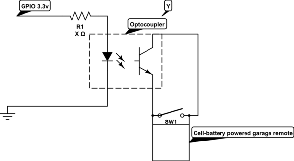
schematic

simulate this circuit – Schematic created using CircuitLab

shorting a remote control pushbutton with GPIO and a transistor

I was referencing this thread, but they've included a 9v battery, and I don't know what purpose that serves.

Alternatively, I could use a relay powered by the 5v Pi output which is triggered by the GPIO, but I worry that the contacts on a relay are too resistive to conduct a small switch short. Please advise!

Thank-you!!

EDIT: Thanks to user Passerby, I now have formula for finding an optocoupler and resistor.

Assuming the Pi outputs 3.3v at 16mA, what's a suitable resistor/optocoupler combination (x & y on schematic)?

\$\endgroup\$
1
  • \$\begingroup\$ Just a note: If you use a photo-transistor optocoupler, you will need to make sure you have the polarity correct when wiring to the switch. If you us a FET optocoupler, like the H11F1, then you don't need to worry about polarity. \$\endgroup\$
    – Mark
    Commented May 30, 2016 at 1:10

2 Answers 2

1
\$\begingroup\$

Aside from an appropriate ballast resistor in series with the led side of the optocoupler r = (3.3 - Vf) / If), yes, that should work.

That post had a remote powered by a nine volt battery. Nothing really changes as far as your concerned with a 3 or 5 volt remote instead.

A relay will work too. The contacts of the relay should only have a negligible resistance (near perfect conductor). But then you have an issue of driving the relay, as the gpio cannot do it directly.

An optocoupler is ideal. But you could just use a simple npn transistor (2n3904). You would have to connect the grounds of the remote and the RPI together.

\$\endgroup\$
7
  • \$\begingroup\$ I'm guessing that the GPIO outputs about 250mA (I don't have a volt meter) and a 4N25 is 60mA, so: r= (3.3 - vf)/0.19. What's the on voltage of a 4N25? (I'm guessing that's the vf?) \$\endgroup\$
    – yeeeeee
    Commented May 30, 2016 at 1:05
  • \$\begingroup\$ The RPI gpio max is 16 mA! \$\endgroup\$
    – Passerby
    Commented May 30, 2016 at 1:10
  • \$\begingroup\$ @yeeeeee the 4n25 normal Vf is 1.3~1.5V at 50mA. The 60 mA is an absolute max. But it should work at lower voltages/currents. For a simple pushbutton setup, it may (should in my opinion) work fine at 16 mA forward current, at which point the Vf is about 1 volt. But you may want to find a better optó coupler. \$\endgroup\$
    – Passerby
    Commented May 30, 2016 at 1:17
  • \$\begingroup\$ So r=(3.3-1)/0.16? 143.75 ohms for the resistor? (Sorry, this is really first time electronics for me) \$\endgroup\$
    – yeeeeee
    Commented May 30, 2016 at 1:22
  • \$\begingroup\$ @yeeeeee no, 16 mA is 0.016 Amps. \$\endgroup\$
    – Passerby
    Commented May 30, 2016 at 2:10
-1
\$\begingroup\$

I believe I've solved the problem. I'll be testing out a ~140 ohm resistor and 4n25 optocoupler.

Other optocoupler/resistor suggestions are greatly appreciated.

\$\endgroup\$
2
  • \$\begingroup\$ Next standard value up is 150Ω. \$\endgroup\$
    – Passerby
    Commented May 30, 2016 at 2:55
  • \$\begingroup\$ This won't put too much draw on the Pi doing all of this? I'm now worried about accidentally pulling more than 16mA from a single pin... \$\endgroup\$
    – yeeeeee
    Commented May 30, 2016 at 2:57

Your Answer

By clicking “Post Your Answer”, you agree to our terms of service and acknowledge you have read our privacy policy.

Not the answer you're looking for? Browse other questions tagged or ask your own question.