4
\$\begingroup\$

I'd like to have redundant power supplies to power an array of four hard drives. Each drive uses 5V at .6A (3W) and 12V at .45A (5.4W), for a total of less than 10W each. The four drives will have data lines to a separate PC which doesn't have the available real estate internally for the four drives, hence the external enclosure.

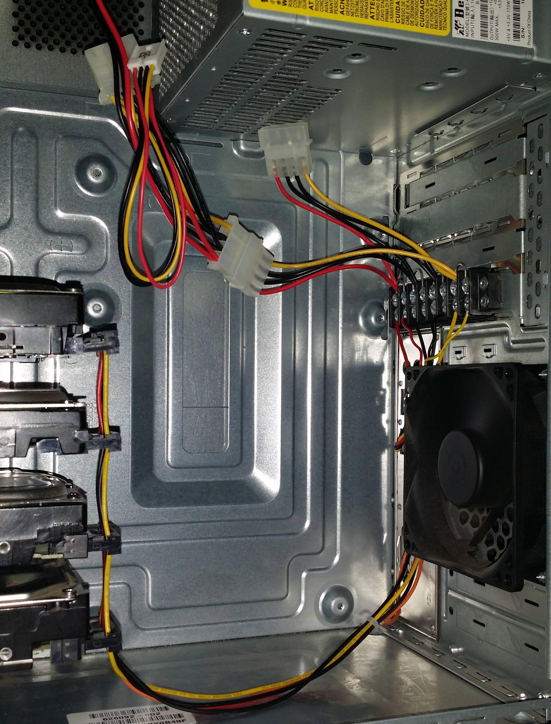
I gutted a PC chassis, installed a cage to hold the drives, made a custom SATA power pigtail, then connected that pigtail to the output from an eight connection (four pair for this purpose) terminal/barrier block riveted to a PCI slot cover (juuuust the right size). I'm using two standard four pin molex connectors to supply power to the input side of the barrier block. The like wires are joined from each molex adapter to one of each pair of input terminals, and each pair on the input side are jumpered, thus supplying three connections at the same potential. I need the additional connections for fans and such.

As it is now, I've only used one power supply. I need to know how to connect two PSs such that they're both on and supplying power, but at any point if one dies the remaining one supplies power to the drive array. I don't want a standby scenario involving relays because the moment of time it takes to switch the relay may cause data loss. I'm okay with both supplying 50% power all the time. The circuit this machine is on has battery backup, so the likelihood of both dying simultaneously is infinitesimal.

See below for an image of the actual setup

Single PS powering a fan and four hard drives

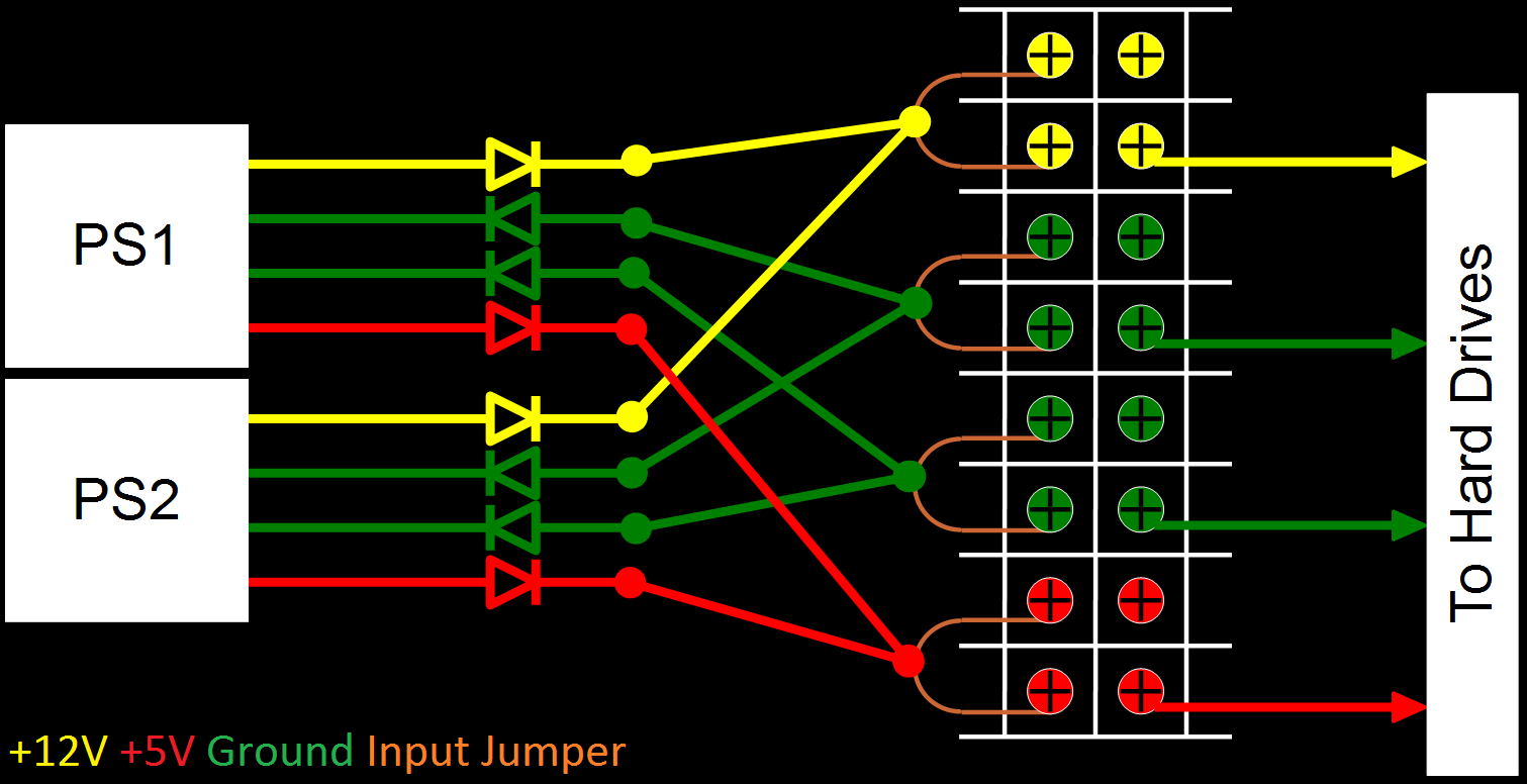
Now to the point of my question. I imagine just tying the like wires together would cause power to feed back (wrong vocabulary?) into a power supply if voltages weren't identical, or when one dies the good one tries to supply current to the bad one. Would soldering diodes on each molex pigtail before the barrier block inputs be suitable to avoid one power supply from feeding current to the other in the event one fails or the voltage fluctuates? If so, how do I select what type of diode to purchase? I can spec a capacitor or resistor, but I've never needed to install a diode in any custom PCB circuitry. See below for proposed schematic.

Proposed Schematic

\$\endgroup\$
5
  • \$\begingroup\$ Diodes on the grounds arnt needed. \$\endgroup\$
    – Passerby
    Commented Jun 2, 2016 at 0:59
  • \$\begingroup\$ I didn't think so, but figured it wouldn't hurt anything. \$\endgroup\$
    – user208145
    Commented Jun 2, 2016 at 1:02
  • 2
    \$\begingroup\$ For a silicon diode, it's typically a 0.7V drop. Two in series, your 12V supply rail just dropped to 10.6V. Your 5V dropped to 3.6V. Significant problem for a hard drive. One may be tolerable. But some may have 1V drop at 2 amps. And this is before we get into issues of the diode bridge setup, or adjusting the input voltage, etc. \$\endgroup\$
    – Passerby
    Commented Jun 2, 2016 at 1:06
  • \$\begingroup\$ You have done well, just omit your diodes on the ground, they are not needed. Use low drop power diodes... If you have unused PC power supply, salvage the diodes from it. \$\endgroup\$ Commented Jun 2, 2016 at 1:10
  • \$\begingroup\$ Proper redundant power supplies use a common ground and FET-based so-called "ideal diodes" to safely and automatically isolate disconnected or failed supplies: see eetimes.com/document.asp?doc_id=1273185&print=yes for some basics. \$\endgroup\$ Commented Jun 2, 2016 at 17:25

4 Answers 4

5
\$\begingroup\$

You do not want to try what you are proposing. Differences in the two power supplies are likely to lead to big ripple or oscillations. And even in the best of situations the two common PC type supplies are not likely to share the current load equally.

Adding the low drop diodes may seem like a good idea at first to isolate the supply outputs from back feeding but it does not prevent the problems mentioned above and could in fact make the problem worse.

Learn from how this is done in the server world where redundant power supplies are common to support maximal up time and hot swap out if a supply fails. Power supplies of this type are designed to work when connected up in parallel. There is a special signal wire that is common across all the supplies that allows management of the load current sharing between the supplies. Load current sharing works better when supplies have a minimal number of output voltages to manage. This is one reason that server power supplies have been reduced to providing just the 5V always on rail and a single 12V rail output. All other voltages needed by the server are produced either on a power distribution board that the redundant supplies connect to or on the server motherboard. (Sometimes a combination of both).

My take on this is that if you purchase a good quality PC power supply, keep it cooled with a good quality fan and regularly blow out all the dust that tends to accumulate over time that the reliability of the power supplies is likely to be better than the hard disk drives. If any thing you may want to consider using a NAS (network attached storage) packaging concept and configure your drives in a simple redundant RAID configuration (i.e. simple whole drive mirroring). Get an enclosure that lets you have your SATA drives in trays that can be easily swapped in and out.

\$\endgroup\$
1
\$\begingroup\$

Adding diodes subtracts a bit of voltage, and wastes power. The best solution is to use a coarse DC supply, at high voltage (24V or 48V are typical), and make THAT redundant (like, one can be a rechargeable battery, one can be an AC driven supply, a third can be a solar array). Then connect the grounds together, and use isolation diodes to a secondary subsystem, a DC/DC converter that takes DC in and generates regulated +12V and +5V outputs.

You can also employ multiple DC/DC converters (each disk having its own), or use multiple modular converters that can be paralleled (this requires a load-sharing scheme, not all converters allow such connection).

Your +12V power probably should handle 1A or so, per drive, because motor startup can require extra power for a short time. There are big-iron sequenced startup schemes, for starting arrays of disks in staggered fashion, that might be of interest.

\$\endgroup\$
1
\$\begingroup\$

I cant comment because I don't have enough reputation (-_-) but this isnt a trivial problem. The PSU's actively monitor the voltage and adjust their output to compensate for changes in current draw, so you might get into a situation where each one is fighting the other and the voltage starts oscillating (not sure how likely that is though, could be interesting to find out). It's unlikely that you'll find a homebrew circuit that will fit your needs, because what you are looking for is ultra-reliability. PSU's are fairly reliable (especially more expensive ones), so the weak link is almost certainly going to be your homebrew circuit.

If you dont mind maybe breaking everything, you could try connecting the two psu's directly. If that works, you then have to consider what might happen if one of the PSU's breaks. If we assume that it's output just becomes disconnected, then everything is fine. If it short circuits, then it will break everything, so maybe you could add a fuse to each of the PSU's, that is well above the max draw of the HDD's (incl the turn on surge), but below the max rating on the PSU. Then if it shorts to ground, the fuse will blow and remove the short.

schematic

simulate this circuit – Schematic created using CircuitLab

Definitely test this before you put data on though.

\$\endgroup\$
-1
\$\begingroup\$

Either use depletion mode mosfets or a logical inverter and enhancement fets back to back. Tie the grounds wire the it so both atx 24pin greens are held down. Use another fet to rig a dummy load on stand by supply.

Back to back can switch ac/acts more like normal switch blocking both directions. This is often referred to as an ideal diode because the v drop is way lower(modern fets rds on is way low)

U might get away with adapting a reverse polarity trick to create your or... Usually done with a single pfet on power input. (because if you connect + to minus terminal she slams shut) like common ground use supply one being on to power gates and keep supply two out of action. I still think nfets with a logical inverter and some chip makers switched cap 100 percent duty cycle isolated gate driver offers best option... More on that in a sec

The back to back fets are probably best on both supplies but might not be absolutely required. Adding benifit would take some more creativity but my thought is that if supply 1 shorts to ground u can remove it from the circuit, a variation would be use fets to control the green wire on both but you would need to tap the 5v standby(always on. Purple iirc) you would want histerisis on gate sig and a lot of other problems /complexities get in the mix here

There is some argument to be had for the inverter, pick it out right and with an rd divider u get more control over when one supply is cut and the other takes over. Aka pick one with a trigger voltage then divide the line u monitor till normal operation is just above threshold. V sag and supply two gets switched in... Again u want hysteresis(tiny cap /rc network) to avoid flipping with say a drive spinning up. Get really creative u can rig over voltage to switch this way too, like another line bypassing the inverter but in some way brought down below iso driver trigger v. Either way id think a schmit trigger could be useful it's purpose is denouncing mechanical switches but here it would serve to give u a more predetermined time u will be with supply two if one chokes. Aka stop rapid flipping back and forth.

Not an ee just like this stuff, use at your own risk. Do your own homework.

\$\endgroup\$
1
  • 2
    \$\begingroup\$ Please use "you" instead of the variable u. \$\endgroup\$
    – Huisman
    Commented Jul 13, 2019 at 19:57

Your Answer

By clicking “Post Your Answer”, you agree to our terms of service and acknowledge you have read our privacy policy.

Not the answer you're looking for? Browse other questions tagged or ask your own question.