You can replace the aluminum electrolytic with a tantalum, but using neither is a much better choice.
Nowadays, ceramics can easily cover the 10 µF at 10s of volts range. There is no point using either a electrolytic or tantalum. You also don't need a separate 100 nF (that value is so 1980s anyway) capacitor if you use a ceramic for the larger value.
Think about what is going on here and what the datasheet is trying to say. These devices are notorious for being quite sensitive to power supply noise. I've actually seen a similar part amplify power ripple from the power supply to the output. The datasheet therefore wants you to put a "large" amount of capacitance on the power line to the device. That's where the 10 µF came from. Back when this datasheet was written, or whoever wrote it stopped keeping up with developments, 10 µF was a unreasonably large request for any capacitor technology that was good at high frequencies. So they suggest a electrolytic for the 10 µF "bulk" capacitance, but to then place a 100 nF ceramic across that. That ceramic will have lower impedance at high frequencies than the electrolytic, despite the fact that it has 100 time less capacitance.
Even in the last 15-20 years or so, that 100 nF could have been 1 µF without being burdensome. The common value of 100 nF comes from the ancient thru-hole days. That was the largest size cheap ceramic capacitor that still worked like a capacitor at the high frequencies required by digital chips. Look at computer boards from the 1970s and you will see a 100 nF disk capacitor next to every one of the digital ICs.
Unfortunately, using 100 nF for high frequency bypass has become a legend on its own. However, the 1 µF multi-layer ceramic capacitors of today are cheap and actually have better characteristics than the old leaded 100 nF caps of the Pleistocene. Take a look at a impedance versus frequency graph of a family of ceramic caps, and you'll see the 1 µF has lower impedance just about everywhere compared to the 100 nF. There may be a small dip in the 100 nF near its resonant point where it has lower impedance than the 1 µF, but that will be small and not very relevant.
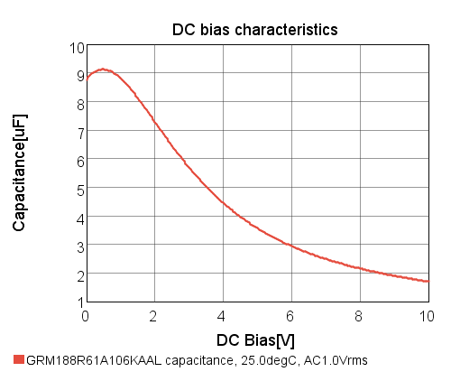
So, the answer to your question is to use a single 10 µF ceramic. Make sure whatever you use still is actually 10 µF or more at the power voltage you are using. Some types of ceramics go down in capacitance with applied voltage. Actually today you can use a 15 or 20 µF ceramic and have better characteristics across the board compared to the 100 nF ceramic and 10 µF electrolytic recommended by the datasheet.

