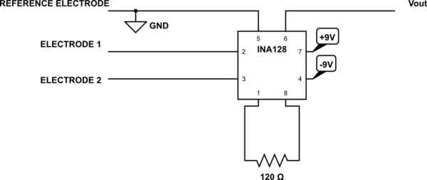
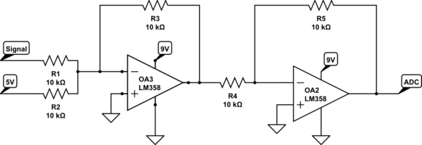
The circuit suggested by you should work in principle. The OP you used (LM741) needs at least \$\pm10V\$ so if you used the same \$\pm9V\$ supply as for the INA128 that may be the error.
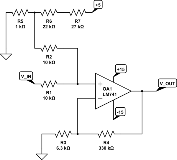
WARNING: MATH For just the solution see circuit below.
If not, here is a circuit I would use to convert the +-100mV to 0-5V using the formula from you link
$$V_0 = \left(V1\frac{R2}{R1+R2} + V2\frac{R1}{R1+R2}\right) \left(1 + \frac{R4}{R3}\right)$$
Lets say \$V1\$ is our input signal and \$V2\$ the Offset Voltage. As you can see in the Formula above we first add then multiply with this circuit just like in math. So to get a positive signal we add \$100mV\$ to the signal. To achieve this we can create a voltage divider with the 5V supply of the Arduino.
$$V2 = 5V \cdot \frac{R5}{R5+R6} = 100mV$$
Using a resistor calculator like this one we get the values for R5 and R6 as:
$$ R5 = 1k\Omega$$
$$ R6 = 22k\Omega + 27k\Omega$$
As you can see R6 is actually created from two resistors in series to match the ratio. Lets call the second Resistor R7
$$ R6 = 22k\Omega$$
$$ R7 = 27k\Omega$$
$$V2 = 5V \cdot \frac{R5}{R5+R6+R7} = 100mV$$
Now to add V1 and V2 without any weighting of the values \$\frac{R1}{R1+R2}\$ and \$\frac{R2}{R1+R2}\$ have to be equal. So in fact R1 has to be equal to R2
Lets chose a value for R1 and R2, say
$$R1=R2=10k\Omega$$
Lets see what we have now:
$$V_0 = \left(V1\frac{10k\Omega}{10k\Omega+10k\Omega} + V2\frac{10k\Omega}{10k\Omega+10k\Omega}\right) \left(1 + \frac{R4}{R3}\right) = \left(V1\frac{1}{2} + V2\frac{1}{2}\right) \left(1 + \frac{R4}{R3}\right) = \left(V1 + V2\right) \frac{1}{2} \left(1 + \frac{R4}{R3}\right)$$
So now that the \$\pm100mV\$ Signal is offset by \$100mV\$ to a range of \$0-200mV\$ we need to boost it to \$0-5V\$
$$\frac{1}{2} \left(1 + \frac{R4}{R3}\right) = \frac{5V}{200mV} = 25$$
$$\frac{R4}{R3} = 49$$
By using the calculator above we get
$$R4 = 330k\Omega$$
$$R3 = 6.3k\Omega$$
This is actually not a perfect fit (3% off) but as resistors can have large margin of error (5%) is is close enough. (You can go better with three resistors: R4=290k R3=10k||39k)
Now we have finally all we need. Final circuit:

simulate this circuit – Schematic created using CircuitLab


