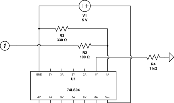
I would like to use a pull-down resistor on the input of a NOT logic gate. I am using a 5V microcontroller, and I want to ensure that the input of the gate will never be floating (eg. microcontroller damage).
General information:
The logic gate I am using is a HD74LS04 inverter whose datasheet can be found here. I am testing the output by placing my positive multi-meter lead on R4 and the negative lead on GND. With the digital pin floating, the output of 1Y is 4.33V. This is the expected behavior.
The logic gate requires a minimum of 2.0V for Vih. If I understand this circuit correctly, I expect the voltage at pin 1A to be 3.76V since R2 and R3 will form a voltage divider. This value seems plenty to signify a 'high' in the logic gate.
R2 exists to protect the digital pin. Ideally, I would have liked R2 to be 1KΩ. Increasing the value of R2 means I have to increase the value of R3 to maintain the same voltage divider. During testing I found that if R3 was any value over 3.3KΩ, the pin 1A would not get pulled down all the way if I left the digital pin floating.
Tests:
If I disconnect everything except GND and Vcc and place the positive lead of my multi-meter on pin 1A (now floating) and the negative lead to GND, I read 1.49V. Placing a pull-down resistor (R3) on pin 1A to GND with a value of 100Ω changes the reading to 0.02V. Increasing the resistor's value to 330Ω increases the reading to 0.07V. At the value I need, 3.3KΩ, the reading increases to 0.60V. Finally, changing the resistor's value to 1MΩ increases the reading to 1.47V and actually changes the output of pin 1Y to low.
The test that uses the 3.3KΩ resistor is concerning. The reading I took (0.60V) seems to be approaching the Vil maximum of the logic gate which is 0.80V.
Questions:
This must be a trivial question, but why does an R3 value of 3.3KΩ not pull pin 1A all the way to GND? Is there a formula for determining the correct pull-down resistor value? Other answers I found on here simply state 10KΩ as a 'good' value for a pull-up resistor. I'm not sure where that value comes from or if it is applicable to a pull-down resistor.

simulate this circuit – Schematic created using CircuitLab
Edit:
Although Ignacio's answer technically answers the question, I thought I would share some information I found for others who may come across this question.
User 'Papabravo' on the All About Circuits form states that the calculation for a pull down resistor can be calculated by taking the Vil (0.8V) and dividing it by the "standard TTL load" of 1.6mA. As Ignacio pointed out, my specific logic gate can source up to 0.4mA, so the calculation would be 0.8/0.0004A which equals 2KΩ. For safety, I performed the calculation at 0.5V in order to give myself some headroom.
Other Resources:
Sparkfun's logic gate tutorial
