1
\$\begingroup\$

In my design, I am connecting an LM324 op-amp in the inverting mode and thus the output voltage would be negative of the input multiplied by th gain. But I am using a 5v and 0V power supply. So how is it possible to get a negative output when my power supply cannot have negative value. Do I need a dual power supply to achieve this?my circuit schematic
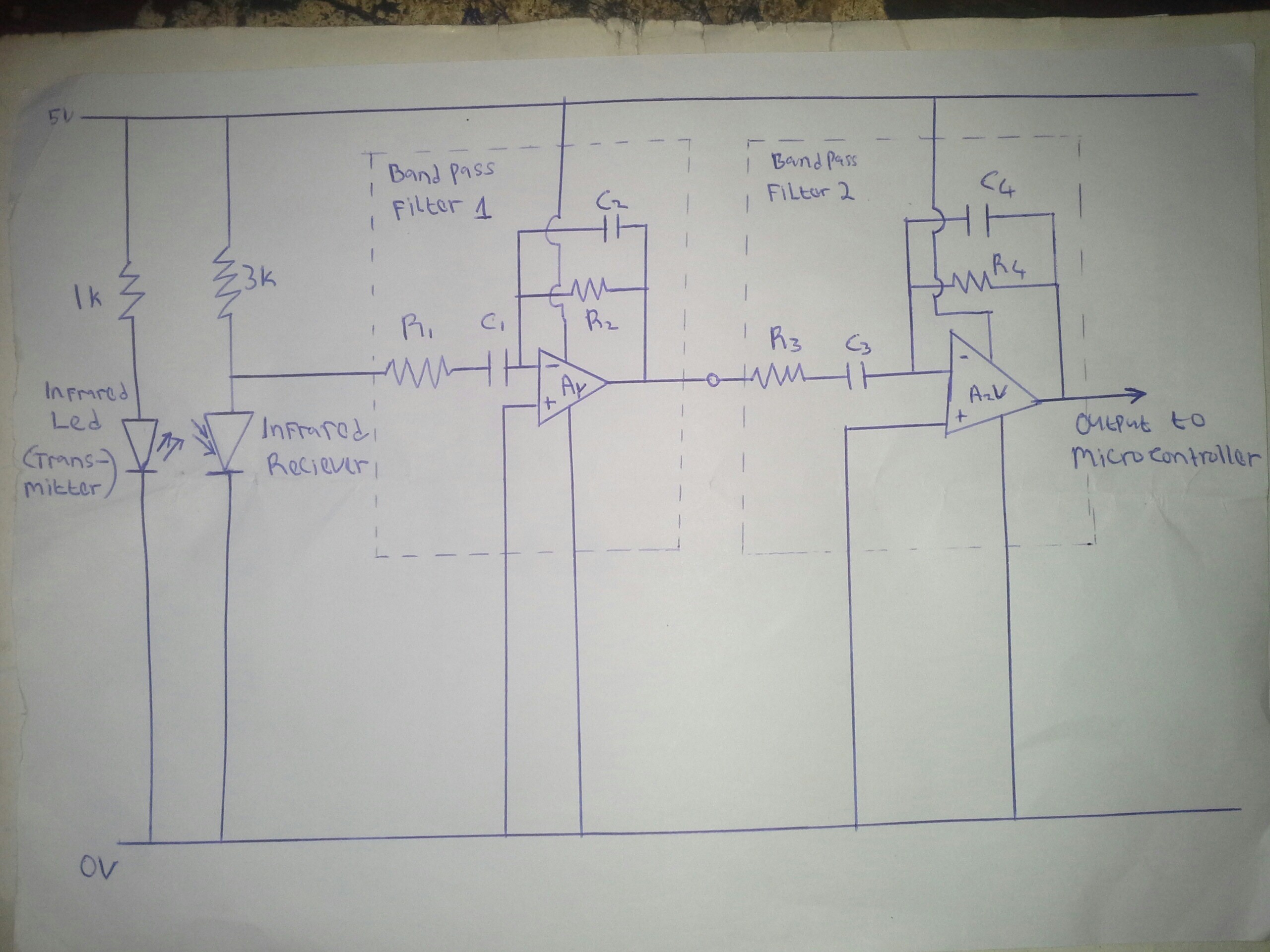
The frequency range of both bandpass filters is from 0.7 hertz to 2.5 hertz. Both op amps should provide enough gain to raise my weak signal (+-0.3v) up to the TTL logic level of my microcontroller I.e around 4.7 v , if not I would add a comparator to do that.

\$\endgroup\$
12
  • 5
    \$\begingroup\$ You can't, and yes you do. \$\endgroup\$
    – brhans
    Commented Jun 6, 2016 at 19:58
  • \$\begingroup\$ Is your input signal AC or DC? \$\endgroup\$
    – EM Fields
    Commented Jun 6, 2016 at 20:00
  • \$\begingroup\$ My input is a constant 2v with a regular +-0.3v fluctuation on top. \$\endgroup\$
    – oziomajnr
    Commented Jun 6, 2016 at 20:06
  • 2
    \$\begingroup\$ You could reference the output to the mid-rails (2.5V), but whether this makes sense depends on your whole circuit. \$\endgroup\$
    – dim
    Commented Jun 6, 2016 at 20:10
  • \$\begingroup\$ Do you need the output to go negative (below 0V) or can it be between 0V and +5V? \$\endgroup\$ Commented Jun 6, 2016 at 21:39

2 Answers 2

4
\$\begingroup\$

You can use a voltage inverter like the LMC7660 to generate a negative rail for your op amp. It converts any voltage between 1.5V and 10V into its negative counterpart -- e.g. +5V in, -5V out. Only good for a few mA though.

\$\endgroup\$
4
  • 2
    \$\begingroup\$ Why the down-vote? Perfectly acceptable answer! \$\endgroup\$ Commented Jun 7, 2016 at 2:22
  • \$\begingroup\$ @Sparky256 The OP specifically asked how to get a negative output -- that was the part of the question I was trying to answer (and that's also the way the title is phrased). \$\endgroup\$
    – tcrosley
    Commented Jun 7, 2016 at 6:27
  • \$\begingroup\$ You could always use a part with the charge pump already on board: maximintegrated.com/en/products/analog/amplifiers/MAX44267.html \$\endgroup\$ Commented Jun 7, 2016 at 8:32
  • \$\begingroup\$ @tcrosley. I missed that one, but the OP had not submitted a diagram yet. But I did miss-interpret the context of the question-and got it backwards. sigh... \$\endgroup\$
    – user105652
    Commented Jun 9, 2016 at 23:03
3
\$\begingroup\$

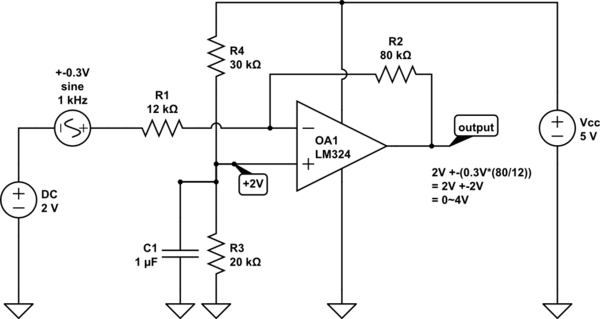
The inverting input of an op amp produces a negative output relative to the non inverting input. So if your signal is 2V +-0.3V then you can set the non inverting input's 'ground' reference to 2V and the output will also be relative to 2V.

schematic

simulate this circuit – Schematic created using CircuitLab

\$\endgroup\$
3
  • \$\begingroup\$ The LM324 struggles to pull down below 0.6V, but without knowing the application we can't say that this will be a problem. The OP didn't specify gain or output voltage limits either, so I just went for the simplest answer. \$\endgroup\$ Commented Jun 7, 2016 at 5:01
  • \$\begingroup\$ I have added a schematic above \$\endgroup\$
    – oziomajnr
    Commented Jun 7, 2016 at 8:03
  • \$\begingroup\$ Signal is AC coupled so no 2VDC to worry about. Just bias each non-inverting input to 2.5V with a resistor divider (like in my circuit) and you are good to go. \$\endgroup\$ Commented Jun 7, 2016 at 8:46

Your Answer

By clicking “Post Your Answer”, you agree to our terms of service and acknowledge you have read our privacy policy.

Not the answer you're looking for? Browse other questions tagged or ask your own question.