I'm thinking about building a monitoring circuit for an existing residential power system. Currently there's a simple ammeter and digital voltmeter in use for some basic monitoring, but nothing fancy.
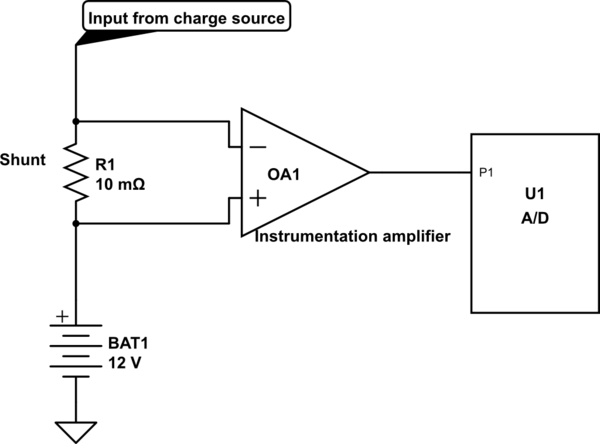
I'd like to augment this with something that supports some history and statistics. I've got some microcontrollers and LCDs lying about that I'd like to use for this, ideally. Here's a slightly simplified schematic for the system I'm thinking about trying building:

simulate this circuit – Schematic created using CircuitLab
Here's my concern: If I'm trying to track power use, then fundamentally, sampling with the A/D converter is giving me a box integration of the voltage difference across the shunt. Now, I can assuage my worries by using an A/D with a really fast sampling rate, but I don't know enough about the charge source input to be able to say how quickly the amperage will be changing. I suppose what I'm worried about is quick current spikes (<100μs) that regular sampling at 10ksps will miss.
What I'm considering is adding some filtering caps to the input, but since the amperage involved is quite high (>= 60A, and the shunt is rated up to 500A so higher peaks are definitely possible) I'm not sure that would be helpful. Am I just being very silly since A/D and amp error will contribute more to overall error than such peaks? Or would throwing a couple of low-ESR 100nF, 47μF, and 470μF caps actually make a significant difference? Is there anything else I should be concerned with? I'm quite the newbie when it comes to analog electronics, so I'm probably missing plenty of silly things. :)
Thanks!
