2
\$\begingroup\$

I have read already quiet a lot about the conductivity of water/ fluids but I cannot find a formula to calculate the resistance between probes in a fluid.

For example:

use-water-as-a-conductor-for-a-circuit-powered-by-1-5v-battery

In the answer Peter Bennett measured about 50.000kOhms.

I would like to know how I can calculate it and what the parameters are.

Parameters I guess so far:

  • average distance of the probes
  • copper surface exposed to the water
  • conductivity of the water (amount of salt for example)
  • volume of the water ??
  • critical voltage or linear??

I will be doing some home experiments with copper/metal in water and measuring the resistance with a small AC/DC current through the water, but I want to calculate it first and then see if I can reproduce the result.

Edit:

I did some small tests with the answers below in mind. Especially the EDLC component was clearly measurable. I did a small test in about 100ml /3.5g salt solution. My findings:

AC: With 5cm /0.2mm probes I got about 70 ohm at 5cm. The amount of probe in the liquid did alter the value. The distance was a key factor, my measurement was not accurate enough to give me a function. Over all very consistent results.

DC: The same probes I first tried with around 1.5V and did notice electrolysis at that point the resistance was low but increased rapidly because of the corroded probes. If I lowered the voltage over the probes to 0.5V the resistance was about 1kiloohm, which was higher than I expected and no visible electrolysis did occur. Please be careful, DC in a salt solution will generate chlorine gas do it in a well ventilated place.

I did the measurements over a voltage divider circuit, will do these again later with a more scientific method and logging, but I did them now to get an overview of what to expect.

I'm still interested in formulas to calculate before I do more tests.

\$\endgroup\$
4
  • \$\begingroup\$ Do you need to use cylindrical probes? The calculation will be much easier if you consider, for example, large flat plates, placed parallel to each other and close together. \$\endgroup\$
    – The Photon
    Commented Jun 17, 2016 at 16:09
  • \$\begingroup\$ ideally I want to calculate it for copper wires. If the results are similar, the copper wires may be simplified to small long flat surfaces. \$\endgroup\$
    – Brett
    Commented Jun 17, 2016 at 16:25
  • \$\begingroup\$ While I don't know any formulas, I do know that the geometry of the probes (sharp vs round, wire vs plate etc.) and the level of impurities both have effects (ultra pure water is actually a great insulator). I know it's not much of an answer, I feel you should know that unless you can measure the impurities in the water, it may be difficult to calculate the resistance beforehand, unless you add a known impurity at a concentration such that it dwarfs the effects of whatever was already in there. \$\endgroup\$
    – Sam
    Commented Jun 17, 2016 at 22:48
  • \$\begingroup\$ Thanks for the answer. I already guessed that it wont be easy to calculate but I would have thought I wasn't the only one who would want to calculate it. About the know impurity, each kind of liquid has a conductivity so that needs to be in the formula so I could calculate it no matter what liquid it is. \$\endgroup\$
    – Brett
    Commented Jun 19, 2016 at 12:18

3 Answers 3

4
\$\begingroup\$

Not an easy problem to solve without modeling software. You have probably noticed that water has a value of resistivity rather than resistance, stated in ohm-meters. This is because the ratio of voltage to current is proportional to the distance and inversely proportional to the cross section of the water.

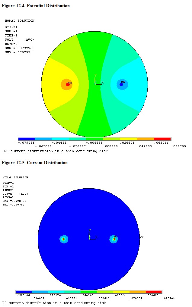
Take a look at the two images below and you can begin to see the problem. The voltage distribution is shown in figure 12.4 and the current density in 12.5. The voltage varies between any two points in the current path, and the current density would also vary if the graph had higher resolution. Then consider that this is a model of a thin disc, and so there is a third dimension that would be present in real life to add complexity. The boundary might be conductive, which would change everything. Finally, the surface area of the conductor in the water will make a difference - the model uses point sources.

Your best bet is to place the water in a vessel of known geometry with electrodes of know geometry and do some modeling or some empirical testing. Bare copper may form a non-conductive oxide layer.

enter image description here

\$\endgroup\$
3
  • \$\begingroup\$ I would already thought the patterns would look like that. if the resolution of the bottom figure would be greater, I suppose you would see an elliptic current pattern between the probes. I would have hoped their would be formulas like Amperes law or Maxwell's equations for magnetic fields to calculate it. \$\endgroup\$
    – Brett
    Commented Jun 19, 2016 at 12:32
  • \$\begingroup\$ Commercial sensors use platinum electrodes surrounded by a non-conductive shroud, but otherwise your approach is sound when you use the AC signal. Get some de-ionized or distilled water, some salt, and an accurate scale and make a solution containing a known quantity of salt per liter of water and do some calibrating. You will want to repeat the calibration occasionally and be sure and thoroughly clean and dry the electrodes between measurements. \$\endgroup\$ Commented Jun 20, 2016 at 13:40
  • \$\begingroup\$ When I worked on this, Aquafina was a good near zero check and Dasani was in the 10-20 range using a calibrated TDS meter. That way we didn't have to play chemistry every time, and those companies spend a lot of money to make sure their water is consistent. \$\endgroup\$
    – Aaron
    Commented Aug 2, 2021 at 20:12
2
\$\begingroup\$

Water is usually characterised by its conductance, and the measurement to determine it is universally AC. The conductivity is generally determined by the amount and type of Total Dissolved Solids (TDS)

Interestingly, the reverse is also true; water cleanliness (or otherwise) can be inferred from the conductivity as it is a measure of TDS in the water.

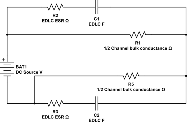
The problem you will have at DC (and I have seen it) is that a metallic conductor (with electrons as the electrical carrier) placed in an ionic solution (the definition of conducting water) is a complex circuit:

schematic

simulate this circuit – Schematic created using CircuitLab

The bulk conductance of the channel varies depending on the constituent salts in the solution; the Atlantic is about 43,000 µS/cm. You can find resources on some common bodies of water here

The EDLC in the diagram forms at the electrode to ionic channel interface.

The value of the EDLC can be enormous - a contact with a circular radius of 5mm may form a capacitor as large as 100µF. Applying a DC source to this contact and then inserting it into the water will cause the classic differentiator waveform that will decay to some level dependent on the bulk conductivity of the water.

This effect was first noticed by Herman von Helmholtz, but the model has been greatly refined.

You can find some help on the calculations here

\$\endgroup\$
2
  • \$\begingroup\$ The electric double layer impedance, which is actually more complicated than that, is in series with the bulk conductance, not in parallel. \$\endgroup\$ Commented Jun 18, 2016 at 17:10
  • \$\begingroup\$ Thanks for the answer, i did notice the effect of the EDLC very clearly in a test I did. Where did you find the circuit you answered? because I do find different circuit just as Massimo reacted. \$\endgroup\$
    – Brett
    Commented Jun 19, 2016 at 15:04
2
\$\begingroup\$

The resistance of water is not linear if you measure the resistance of tap water with a fluke meter for instance you will get a very high value because the voltage used with the meter is very low ---If you apply for instance 5VDC to the water and measure the current flow and use ohms law to calculate the current you will find the resistance to be much lower.

\$\endgroup\$

Your Answer

By clicking “Post Your Answer”, you agree to our terms of service and acknowledge you have read our privacy policy.

Not the answer you're looking for? Browse other questions tagged or ask your own question.