I need help with the following problem:
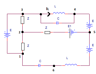
Given the circuit of sinusoidal current (attachment 1) with given data: $$\underline{E}=100V,\underline{E_1}=40V,\underline{Z}=(10+j10)\Omega,\omega=10^5rad/s,L=1mH,$$ $$C=0.1uF.$$ Find $$\underline{I_L},\underline{U_{16}}$$, active and reactive power in the branch 2-5.
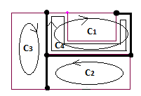
Using the loop current analysis we can find four loops (attachment 2) that correspond to linear system of four complex equations:
$$C_1: (2\underline{Z}+jX_L)\underline{I_{C1}}-\underline{Z}\underline{I_{C2}}-\underline{Z}\underline{I_{C3}}+\underline{Z}\underline{I_{C4}}=\underline{E_1}-\underline{E}$$
$$C_2: 2\underline{Z}\underline{I_{C2}}-\underline{Z}\underline{I_{C1}}+\underline{Z}\underline{I_{C3}}+\underline{Z}\underline{I_{C4}}=\underline{E_1}+\underline{E}$$
$$C_3: 2\underline{Z}\underline{I_{C3}}-\underline{Z}\underline{I_{C1}}+\underline{Z}\underline{I_{C2}}-\underline{Z}\underline{I_{C4}}=\underline{E}$$
$$C_4: (2\underline{Z}-jX_C)\underline{I_{C4}}+2\underline{Z}\underline{I_{C1}}+\underline{Z}\underline{I_{C2}}-\underline{Z}\underline{I_{C3}}=\underline{E_1}-\underline{E}$$
This gives: $$(20+j120)\underline{I_{C1}}-(10+j10)\underline{I_{C2}}-(10+j10)\underline{I_{C3}}+(20+j20)\underline{I_{C4}}=-60$$
$$(-10-j10)\underline{I_{C1}}+(20+j20)\underline{I_{C2}}+(10+j10)\underline{I_{C3}}+(10+j10)\underline{I_{C4}}=140$$
$$(-10-j10)\underline{I_{C1}}+(10+j10)\underline{I_{C2}}+(20+j20)\underline{I_{C3}}+(-10-j10)\underline{I_{C4}}=100$$
$$(20+j20)\underline{I_{C1}}+(10+j10)\underline{I_{C2}}-(10+j10)\underline{I_{C3}}+(20-j80)\underline{I_{C4}}=-60$$
After reducing to 3x3 system:
$$(30+j230)\underline{I_{C1}}+(-10-j10)\underline{I_{C3}}+(50+j50)\underline{I_{C4}}=20$$
$$(10+j110)\underline{I_{C1}}+(10+j10)\underline{I_{C3}}+(10+j10)\underline{I_{C4}}=20$$
$$(40+j140)\underline{I_{C1}}+(-20-j20)\underline{I_{C3}}+(40-j60)\underline{I_{C4}}=-120$$
After reducing to 2x2 system:
$$(40+j340)\underline{I_{C1}}+(60+j60)\underline{I_{C4}}=60$$
$$(-20-j320)\underline{I_{C1}}+(-60-j160)\underline{I_{C4}}=-160$$
$$ \begin{bmatrix} 40+j340 & 60+j60 \\ -20-j320 & -60-j160 \\ \end{bmatrix} \begin{bmatrix} \underline{I_{C1}} \\ \underline{I_{C4}} \\ \end{bmatrix}=\begin{bmatrix} 60 \\ -160 \\ \end{bmatrix}\Rightarrow $$
$$\begin{bmatrix} 40+j340 & 60+j60 & 60+j0 \\ -20-j320 & -60-j160 & -160+j0 \\ \end{bmatrix}=$$
$$\begin{bmatrix} 40 & -340 & 60 & -60 & 60 & 0 \\ 340 & 40 & 60 & 60 & 0 & 60 \\ -20 & 320 & -60 & 160 & -160 & 0 \\ -320 & -20 & -160 & -60 & 0 & -160 \\ \end{bmatrix} $$
Reduced row echelon form of this matrix is: $$\begin{bmatrix} 1 & 0 & 0 & 0 & 1275/7481 & -240/7481 \\ 0 & 1 & 0 & 0 & 240/7481 & 1275/7481 \\ 0 & 0 & 1 & 0 & 303/7481 & 7688/7481\\ 0 & 0 & 0 & 1 & -7688/7481 & 303/7481 \\ \end{bmatrix}$$
Now:
$$\underline{I_{C1}}=\frac{1275}{7481}+j\frac{240}{7481},\underline{I_{C4}}=\frac{303}{7481}-j\frac{7688}{7481}\Rightarrow \underline{I_{C3}}=\frac{8209}{7481}-j\frac{15089}{7481},$$$$\underline{I_{C2}}=\frac{22565}{7481}-j\frac{14675}{7481}$$
$$\underline{I_L}=\underline{I_{C1}},\underline{U_{16}}=-jX_C \underline{I_{16}},\underline{I_{16}}=\underline{I_{C2}}\Rightarrow \underline{U_{16}}=-\frac{1467500}{7481}-j\frac{2256500}{7481}$$
Active and reactive power in the branch 2-5 can be found by complex apparent power, $$\underline{S_{25}}=\underline{U_{25}}\underline{{I_{52}}^{*}}$$
$$\underline{I_{52}}=\underline{I_{C1}}+\underline{I_{C2}}+\underline{I_{C3}}=\frac{32049}{7481}-j\frac{29524}{7481}$$ $$\underline{U_{25}}=\underline{E_1}-\underline{I_{52}}\underline{Z}=-\frac{316490}{7481}-j\frac{25250}{7481}\Rightarrow \underline{S_{25}}=-\frac{9397707010}{55965361}-j\frac{10153288010}{55965361}$$
$$\Rightarrow P=-\frac{9397707010}{55965361} W,Q=-\frac{10153288010}{55965361} var$$
Question: Could someone check if the results are correct?
UPDATE:
Question: What type of simulation in OrCAD Capture CIS Lite 16.6 can be used for checking these results?


