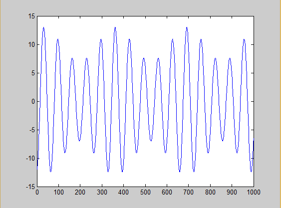
In an AM wave what is the reason behind shape of envelope? why does a mirror image of modulating wave appear below the axis as well?
-
1\$\begingroup\$ Consider reading up on Wikipedia. Essentially: that's how AM works when appropriately under-modulating the carrier, allowing for carrier recovery. \$\endgroup\$– user2943160Commented Jul 11, 2016 at 7:01
-
\$\begingroup\$ In practical applications, where the carrier is very much higher in frequency than the modulating signal, the carrier looks like a blur and the amplitude of the blur is the modulating signal. The blur is symmetrical about the horizontal, time axis. \$\endgroup\$– ChuCommented Jul 11, 2016 at 7:45
-
\$\begingroup\$ You are given a channel where you can transmit and receive at a certain frequency. But you might want to transmit signals at a much lower frequency - audio frequency - and you can't either because you are not allowed by law to use a different frequency or because the channel is not good at different frequencies (the medium might attenuate too much of the radiation). So you use a carrier at the frequency required by the channel. One way to transmit information is by modulating the amplitude of such carrier. Bottom line: carrier->required by channel, modulation->carry information. \$\endgroup\$– Sredni VashtarCommented Jul 11, 2016 at 8:24
-
2\$\begingroup\$ AM = amplitude modulation. Surely these words alone define the shape. \$\endgroup\$– Andy akaCommented Jul 11, 2016 at 8:37
-
\$\begingroup\$ Also: electronics.stackexchange.com/questions/211652/… \$\endgroup\$– Sredni VashtarCommented Jul 11, 2016 at 8:40
3 Answers
It is not really an exact mirror. It looks like that because the frequency of the carrier is normally much bigger than the frequency of the AM modulating signal. For example for AM radio it is at least 525 kHz for the carrier and 5kHz for the modulating signal, a ratio > 100.
The modulating signal is multiplying the carrier all the time. When the carrier wants to reach its positive maximum, it not always 'can' because it is limited by the value of the modulating signal.
When the carrier wants to reach its negative maximum, again it sometimes 'can't' because it is limited by the modulating signal.
See this simulation of AM for fc = 5 fm. It is not an exact mirror:
As fc gets bigger, the envelope looks more and more like a mirror but it is never a completely equal mirror
It depends what is being plotted.
If the amplitude (a low frequency signal representing the modulation) is being plotted, then you see a single trace.
If the modulated carrier (a variable amplitude high frequency signal) is being plotted, then the trace goes above and below the zero volt axis, producing the mirror image you describe.
Because the AM signal is AC coupled. It is generated via a high pass filter that eliminates both the DC and baseband components (or usually a bandpass filter centred on the carrier frequency, with bandwidth at least twice that of the baseband (modulating) signal. (Some "balanced modulators" eliminate the baseband component by other means)
If you add the baseband signal to the AM signal at the correct amplitude, you will see all negative peaks at the same amplitude and all positive peaks tracing out the baseband signal, but now at twice the amplitude.

