0
\$\begingroup\$

I'm working (slowly) on a project to build a curve tracer based largely on the Heathkit original (Heathkit Catelogue - IT-1121) and I've come up against an issue in the step generating circuit.

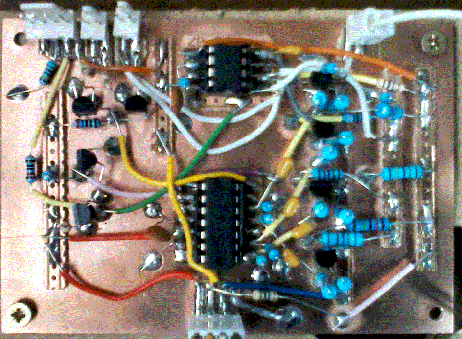
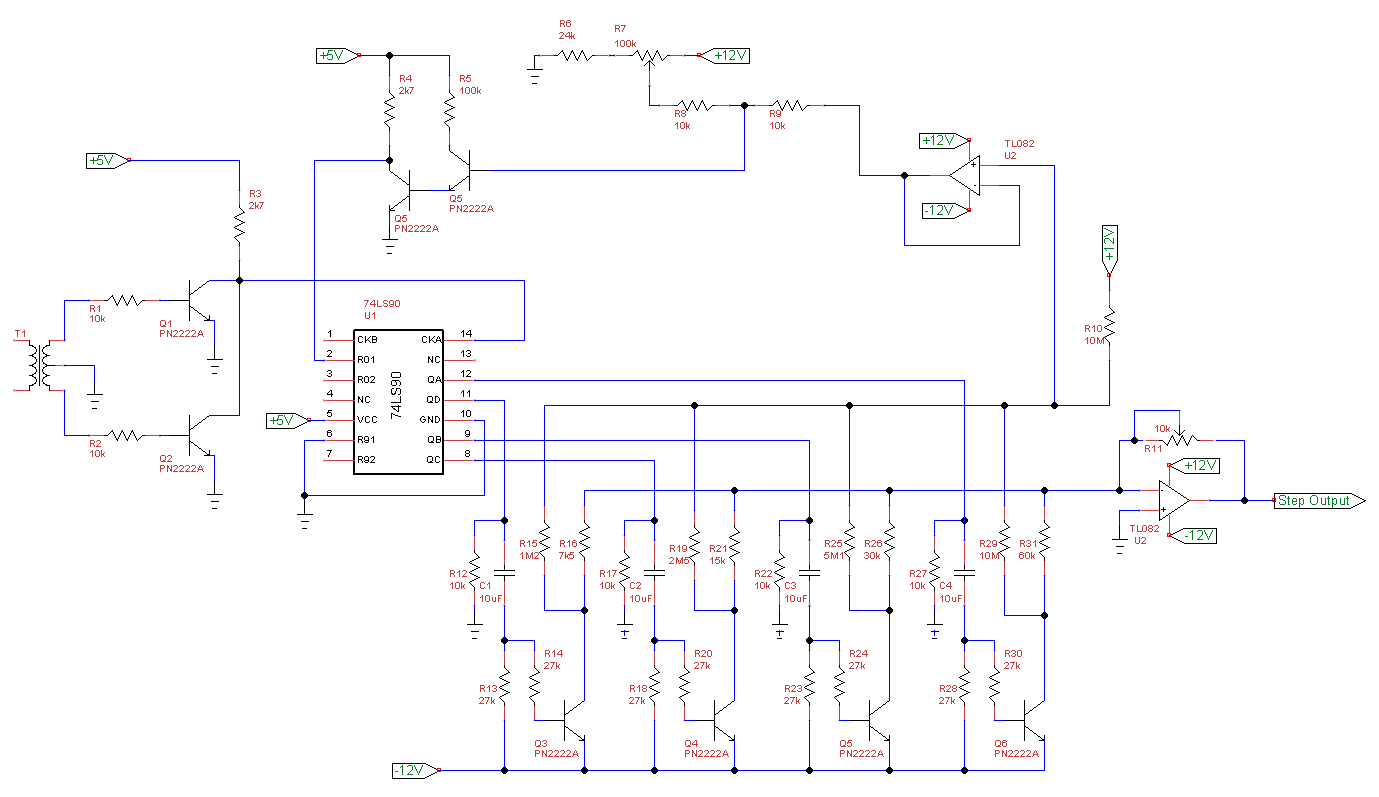
Implemented Cicuit

The issue is with the step reset logic which produces a spike at the end of the selected sequence of steps. It took me a while to twig what the issue was, but the basis of the design is that the reset circuit "sees" the next step before the reset is triggered. The consequence of this is that the smallest spike of the n+1 step is produced at the output.

Clearly I can't have these spikes messing up my DUT base/gate signal and I'm assuming this issue existed in the original. To my annoyance, I missed this at the breadboard stage (I did notice the spikes, but I put it down to stray inductance). Right now I'm thinking I should re-build the section completely, most likely using a microprocessor. But, before I (reluctantly) abandon this board, can anyone suggest an alteration that would remove the spikes? One thought I had was to reset using the NOR gate pulses - so instead of looking at the output, I count the input pulses and reset on the rising edge (given that the counter IC increments on the falling edge).

Note: careful observers will notice that I've altered the reset circuit slightly to avoid having to use the (impossible to obtain 7M5 POT), but I'm pretty sure the update retains the original idea.

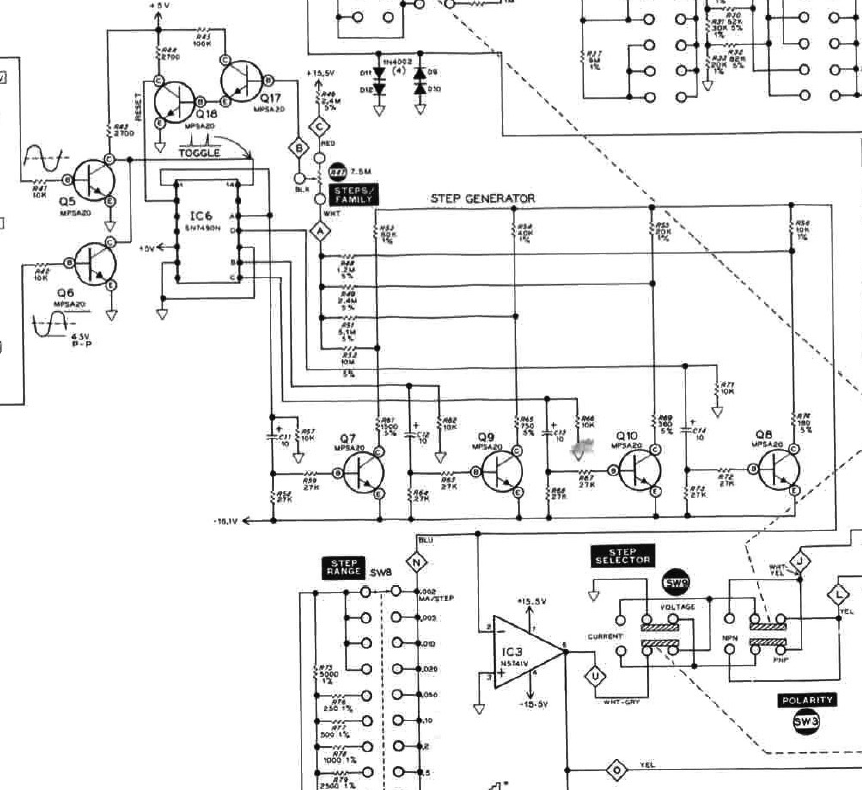
Original Circuit enter image description here

\$\endgroup\$
9
  • 2
    \$\begingroup\$ "Clearly I can't have these spikes messing up my DUT ..." Why not? What problem does this actually cause? It occurs at a time when there's no drain/collector voltage anyway. \$\endgroup\$
    – Dave Tweed
    Commented Jul 12, 2016 at 11:10
  • \$\begingroup\$ Ah? Good point! Are you saying that the sweep voltage will have passed its peak and be heading through the zero crossing at this point? \$\endgroup\$
    – Buck8pe
    Commented Jul 12, 2016 at 11:17
  • \$\begingroup\$ Yes, that's the whole point of the two transistors that drive the clock input of the counter. \$\endgroup\$
    – Dave Tweed
    Commented Jul 12, 2016 at 11:19
  • \$\begingroup\$ Great point and I think you've just saved me a "lot" of work. I'm testing these components as I go and I hadn't considered the joined up effects, as it were. Good catch. \$\endgroup\$
    – Buck8pe
    Commented Jul 12, 2016 at 11:23
  • 1
    \$\begingroup\$ @Brian, I think I understand what you're saying - you're suggesting that the jfet would react quicker to the rising edge of the counter, allowing the reset to kick-in faster, right? If the spike continues to be a nuisance despite what dave says, I'll consider this as an improvement. \$\endgroup\$
    – Buck8pe
    Commented Jul 12, 2016 at 12:38

2 Answers 2

1
\$\begingroup\$

I think your main problem is that the reset is asynchronous.

Unfortunately your counter doesn't offer a synchronous reset, so the only real solutions I see are

  1. to buffer your counter outputs with flip-flops or
  2. to use a counter that has synchronous reset capabilities (e.g. TI SN74LS163).

To mitigate your issue, you might be able to reduce the spikes by fine-tuning your compare level (I think that's what R7 in your schematic does), but you might have already done that.

Apart from that, using a very fast comparator with a well adjusted compare level instead of your transistor circuit might allow you to further reduce the spikes.

You can also try to add a flip-flop to synchronize your reset-signal to the main clock, but that might not be faster than the comparator.

However, the real issue is your asynchronous reset logic of your counter, so some spikes will always be present.

// update: Although using the opposite edge to reset your circuit is a nice idea, it won't help in this case as this would cut off half of the last step (because the reset happens instantly, even at the 'wrong' clock edge).

\$\endgroup\$
2
  • \$\begingroup\$ The flip-flop buffer sounds like a good suggestion - I hadn't thought of cleaning up the output like that and I'm wondering now if I could implement a follow on component that discriminated between a 50Hz pulse and a shorter one (eliminating the shorter pulse). Hmmm? \$\endgroup\$
    – Buck8pe
    Commented Jul 12, 2016 at 11:12
  • \$\begingroup\$ I think it's better to change to synchronous logic than to 'identify' the glitches in your logic and filter them out. You would clock the flip flops with the clock of your counter. Chances are good that the short spikes will be too late and to short to fall into the setup and hold times of the flip-flops. Using that approach you stay mostly independent of your clock frequency. Note however, that this will delay your output by one clock cycle. You can also use the counter I mentioned, might be easier and avoids the delay. If you're lucky, as @dave-tweed said, you can ignore this issue. \$\endgroup\$
    – cx05
    Commented Jul 12, 2016 at 11:25
1
\$\begingroup\$

I came here just looking for a completely different problem but the keyword reset brought me here ;-)) It's quite obvious that the design is done in a way to act as you say. What triggers the rest is the voltage PRESENT at the output of the very complex reset circuit ;-(( What I mean is that you MUST generate the next step voltage to get to a voltage that would cause the reset. So it's designed to work that way, sorry to say that ;-((

What you could do is to put a little 100 to 1000pF capacitor across R11. this would act a s little integrator then slowing down quick transients on the OUTPUT of the step generator. It would not act on the reset line(circuitry). In this way the reset will trigger faster than the change of level ont the generator output. The capacitor must be selected based on how much you can accept of the glitch. Good luck. To day a much simpler circuit could be built. Suggestion, replace the 90 with a 93 and you'd have a 16 step generator ;-))

\$\endgroup\$
1
  • \$\begingroup\$ Good idea Gianni, however I completed this project some time back. Actually, the complete circuit works well enough and as Dave says, the glitch is an accepted part of the design since it occurs outside the critical measurement period. \$\endgroup\$
    – Buck8pe
    Commented Nov 23, 2016 at 12:03

Your Answer

By clicking “Post Your Answer”, you agree to our terms of service and acknowledge you have read our privacy policy.

Not the answer you're looking for? Browse other questions tagged or ask your own question.