This is for a Raspberry Pi AVR ISP interface board. Most of the functionality is around level shifting the logic to the target board's voltage. This is achieved with a 74ABT125 chip. It's powered by an AP2331 that is fed from a switch which feeds either 3.3v, 5v or nothing (in which case the buffer chip is expected to be powered by the target.
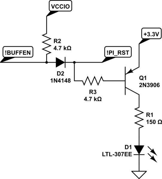
Of concern is one small portion of the circuit:

simulate this circuit – Schematic created using CircuitLab
VCCIO is the output of the AP2331. It's fed into the Vcc line of the '125 and a couple of other 4.7k pull-up resistors that have diode-resistor level shifters for the MOSI and SCK lines from the Raspberry Pi. !BUFFEN is the output enable line on the '125. !PI_RST is the GPIO pin on the Raspberry Pi that initiates programming. It normally floats, but is asserted to 0 (ground) to reset the target.
Note that the actual programming functionality of this circuit works perfectly. It's just the LED - which is supposed to indicate programming is active - that isn't working.
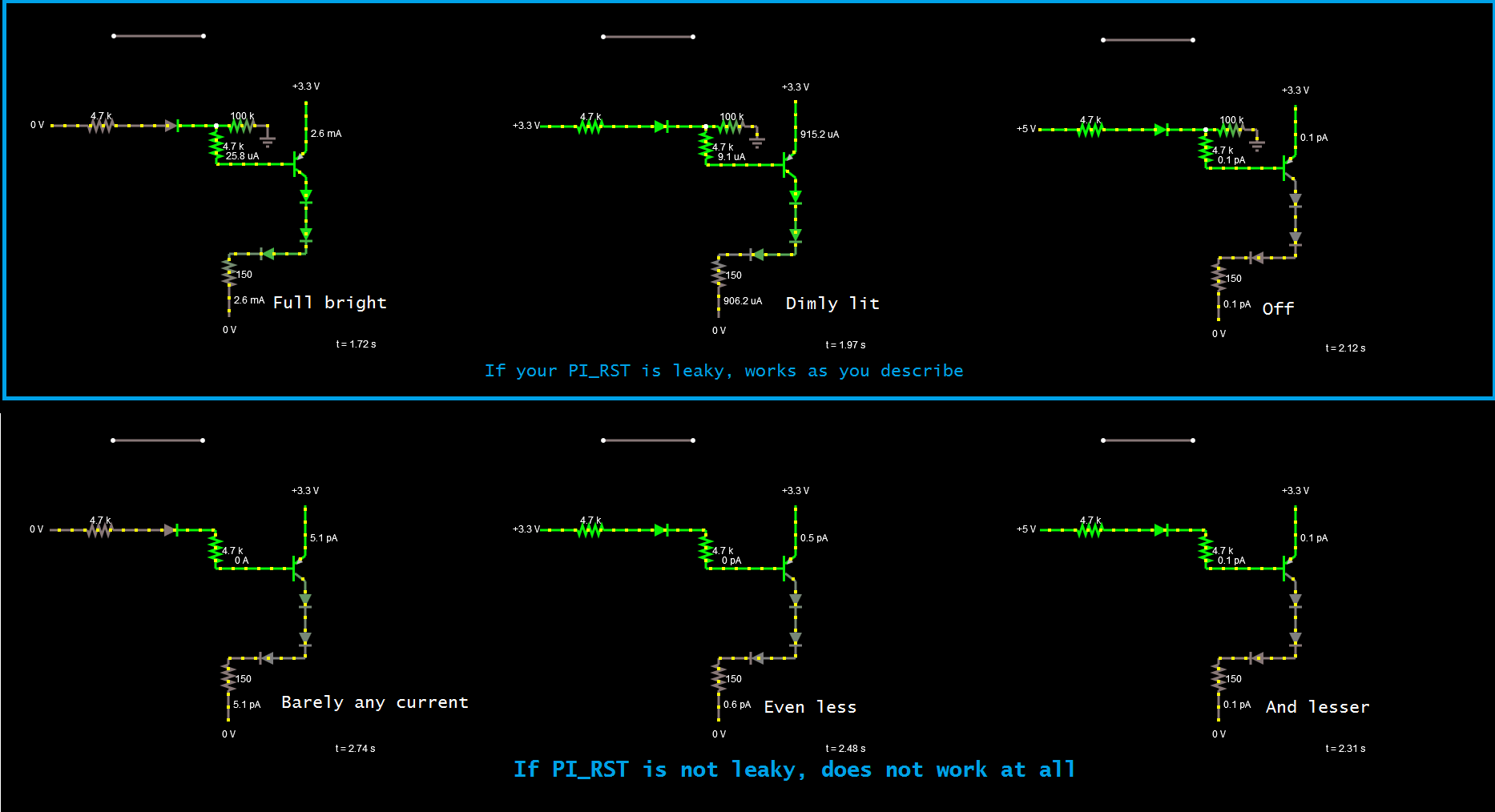
What's going on is that when the system is idle and the power switch is set for 5 volts, the LED is out, as you'd expect. When the power switch is set for 3.3 volts, the LED glows at something like 1/3 brightness. When the power switch is set for no power, the LED turns on.
Clearly some sort of current path exists through the transistor when the switch isn't set for 5 volts.
I've tried cranking the base resistor up to 200k, but that didn't change anything. What I do notice from doing that is that the LED sort of fades in - probably because the bypass cap across the power supply pin for the '125 is charging up.
I can try cranking up the resistance of the VCCIO pullup resistor - that particular signal doesn't need to be particularly fast.
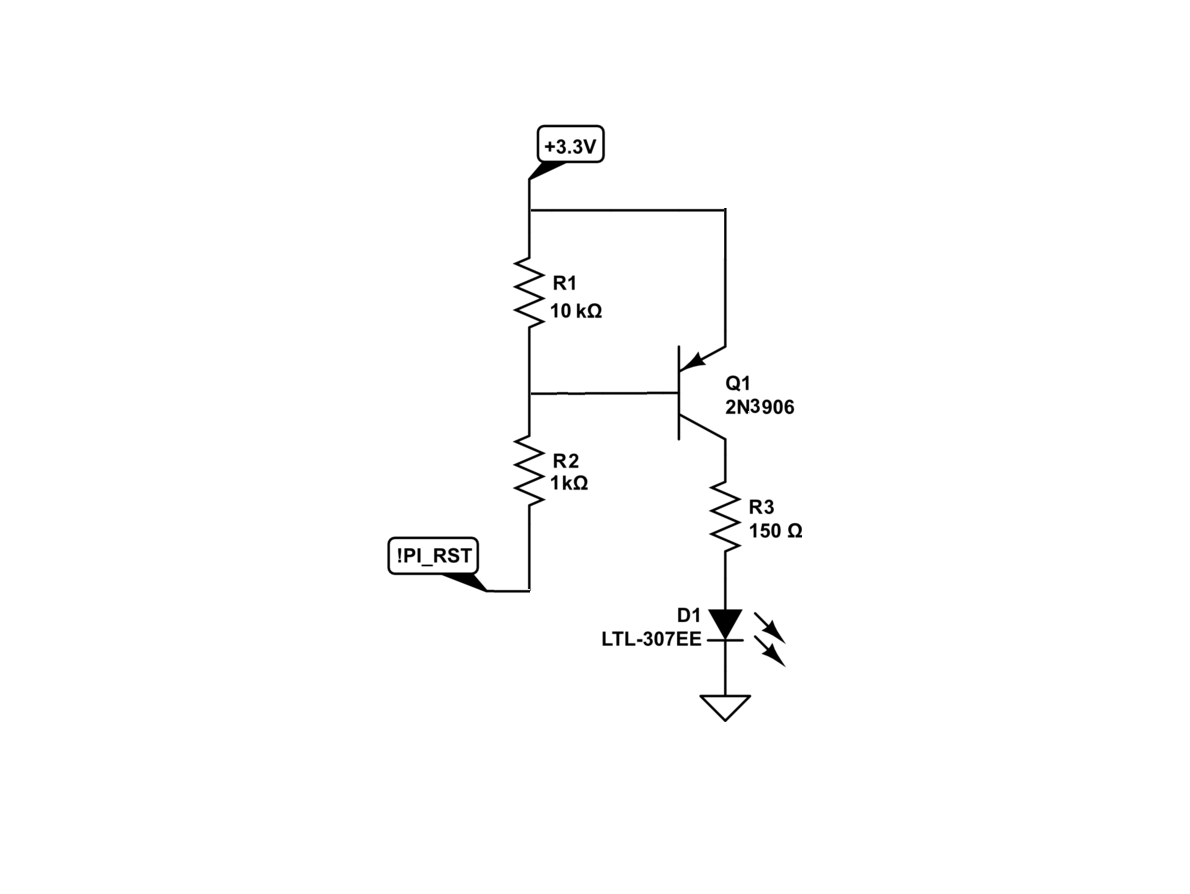
Anybody have any other ideas how to make this LED act as intended - turning on only when the !PI_RST line is grounded?


