3
\$\begingroup\$

enter image description here

I am making a battery tester, for lithium ion batteries in particular.

I want to measure the internal resistance, but after testing few cells, I am skeptical of my results. Most of them, new or old are around 500-800 mOhm, totally not close to 150 mOhm range as it should be.

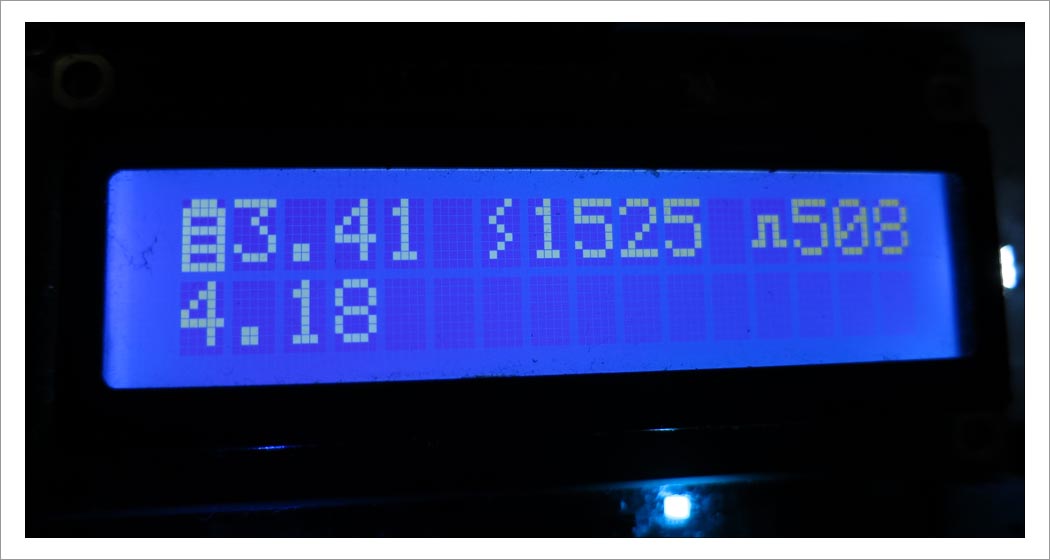
The photo: For this instance, the open voltage is 4.18V and load voltage is 3.41V with 1525 mA discharging current; 4.18V-3.41V/1.525A= 0.504 ohm;

Is this the correct way to measure internal resistance? Since new and old cells all have similar result, is it safe to say that internal resistance is irrelevant to the health of a li-ion cell?

\$\endgroup\$
7
  • 2
    \$\begingroup\$ 1525mA is on the high side for battery discharge. The resistance will be higher with higher currents. Try at 500mA or so. Also, you should use a lowercase m for milli. M implies Mega = million \$\endgroup\$
    – jbord39
    Commented Jul 20, 2016 at 5:22
  • 1
    \$\begingroup\$ 100ma to 1500ma, similar results. \$\endgroup\$
    – user83582
    Commented Jul 20, 2016 at 5:24
  • 1
    \$\begingroup\$ The method seems right but yes, the numbers also seem high. Is it freezing cold where you are doing these measurements :P? \$\endgroup\$
    – jbord39
    Commented Jul 20, 2016 at 5:34
  • 1
    \$\begingroup\$ 25C here. I am a squirrel, not a penguin. \$\endgroup\$
    – user83582
    Commented Jul 20, 2016 at 5:44
  • 3
    \$\begingroup\$ Have you compensated for leads and connectors? \$\endgroup\$
    – pjc50
    Commented Nov 7, 2017 at 12:07

3 Answers 3

8
\$\begingroup\$

No, the method is not correct at all (if you wish to duplicate manufacturer's specifications). There are two ways. Apply a 1 kHz sine wave current to the battery. Measure V and I at 1kHZ to calculate R. The current should be small, but large enough to get a useable reading on your oscilloscope. Use AC coupling so you can see mV readings. Use a sense resistor on the low side of the battery to measure current.

The second way is to apply a low-duty cycle step current load. Measure the instantaneous voltage drop at the moment the step load turns on (you need an oscilloscope to do this). The load could be, say, C/10 or C/5. I usually do this with a function generator, a resistor, and a FET. The function generator turns the FET on. The resistor is attached so when the FET turns on, it becomes a load current to the battery. The resistance is calculated using V/I = R, where V is the voltage change, and I is the step load current value.

If you measure the load voltage and no-load voltage with a slow instrument such as a battery analyzer, you will be measuring load droop caused by chemical rate effects at the anode and cathode. I guess this number could be meaningful, but it is not how the manufacturer measures internal resistance.

\$\endgroup\$
6
  • \$\begingroup\$ How is this method incorrect? He is not asking how to measure the high frequency impedance. The setup he mentioned is a common method, even looking at the wikipedia article shows this an accepted way... en.wikipedia.org/wiki/Internal_resistance#Battery \$\endgroup\$
    – jbord39
    Commented Jul 20, 2016 at 6:00
  • 2
    \$\begingroup\$ hk-phy.org/energy/commercial/act_int_resist_e.html Another reference shows nearly his exact method with a second resistance value. And a peer reviewed paper showing his method with the addition of a single data point in the discharge curve (see equation 2): ncbi.nlm.nih.gov/pmc/articles/PMC3247723 Maybe I am misunderstanding something but "not correct at all" seems harsh. \$\endgroup\$
    – jbord39
    Commented Jul 20, 2016 at 6:17
  • 2
    \$\begingroup\$ It is not correct because it does not produce the same result as the industry standard method used to rate battery impedance. The goal of the standard method is to characterize impedance of a resistive nature, not to characterize effects related to chemical reaction rates at the anode and cathode. The voltage drop caused by a persistent DC load is a chemical effect that can't really be called "resistance." \$\endgroup\$
    – user57037
    Commented Jul 20, 2016 at 6:18
  • 5
    \$\begingroup\$ The second method I suggested relies on the load resistance concept. But you have to measure the instantaneous drop at the moment the load is applied. The display of the battery analyzer is too slow. The OP did express confusion about why the results do not agree with the readings supplied by the vendors. My answer addresses that. \$\endgroup\$
    – user57037
    Commented Jul 20, 2016 at 6:22
  • 1
    \$\begingroup\$ Actually in the first way you measure internal impedance and in the second internal resistance. There is a great article explaining it batterybro.com/blogs/18650-wholesale-battery-reviews/… \$\endgroup\$
    – Slava
    Commented Jan 22, 2021 at 17:49
4
\$\begingroup\$

It depends on what you mean by internal resistance. The "effective" resistance can be measured from the DC current and DC voltage drop. However, as pointed out by mKeith, the DC voltage drop, \$dV_{DC}\$ has two parts:

\$dV_{DC} = V_{drop} + I*R\$

\$V_{drop}\$ is a voltage drop caused by drawing the current I, but it is different than the ohmic resistance R. If you want to know how much power is wasted as heat, that number is \$I^2 *R\$. mKeith points out 2 different ways of measuring R. One is using an AC voltage. Many battery spec sheets report R at 1 kHz. However, this value of R is typically less than the DC value of R, due to the finite capacitance of the cell. The second method recommended by mKeith is to measure the instantaneous voltage drop when a DC current is turned on. This method will give the DC value of R, as long as the measurement is not truly "instantaneous". You want to wait long enough, say 0.1 s, for the battery capacitance to fully charge, but not so long that the voltage drop appears. These effects are discussed in detail in the reference provided by jbord39 (http://www.ncbi.nlm.nih.gov/pmc/articles/PMC3247723/). However, a careful reading of the paper shows that contrary to the assertion of jbord39, the authors specifically state that just measuring the DC voltage drop is not sufficient for obtaining R. Note that Figure 3 has a good illustration of the voltage drop. A load is applied at 10 seconds and removed at 30 seconds. However, the battery voltage at 31 seconds is less than the voltage at 9 seconds, even though the current is 0 in both cases. This is partly due to the voltage drop as the state of charge of the battery decreases, but also due to the voltage drop caused by a change in the chemical state of the battery. The voltage slowly increases with time from 31 to 65 seconds as the battery slowly returns to its original chemical state.

\$\endgroup\$
0
\$\begingroup\$

the correct way to measure the resistance is to start with a small preload constant load eg 100 -200 ma and then add the rest 800 mA to reach 1 amp.
so now u have the change in voltage for an 800mA load. now calculate dV/dI= internal resistance.

\$\endgroup\$
1
  • 5
    \$\begingroup\$ Please take the effort to write properly. The first letter in a sentence should be capitalized and "you" is spelled with a "y" and an "o". \$\endgroup\$
    – Oskar Skog
    Commented Nov 7, 2017 at 6:30

Your Answer

By clicking “Post Your Answer”, you agree to our terms of service and acknowledge you have read our privacy policy.