3
\$\begingroup\$

My question is simple.

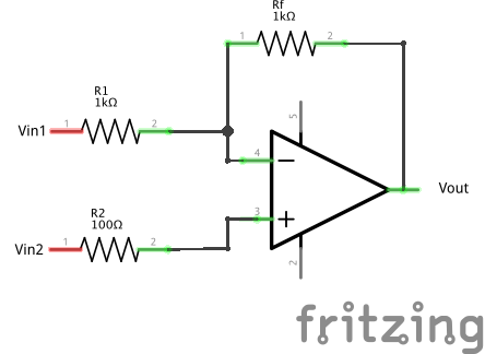
Let's say Vin1 = 5V and Vin2 varies from 0 to 5V.

What is Vout, if the non-inverting input is not connected to ground (with or without a resistor between the + input and ground)?

In the case of a difference amplifier, standard texts always show the non-inverting input connected to ground via a resistor (Rg). In that setup, Vout is trivial, but what about the setup shown below?

Your help is appreciated!

Note: Assume that the + and - supply terminals (2 and 5) in the diagram are wired up.

enter image description here

\$\endgroup\$
5
  • \$\begingroup\$ Do you know how to analyze such a circuits? (well, you need a reference voltage somewhere, right?) \$\endgroup\$
    – Eugene Sh.
    Commented Jul 22, 2016 at 14:10
  • \$\begingroup\$ Well, if the non-inverting input is grounded, then Vout can do what is necessary to make the difference between the inputs equal to zero (so that V+ = V-). This setup confused me a bit. \$\endgroup\$ Commented Jul 22, 2016 at 14:14
  • \$\begingroup\$ Exactly. Just use this property of negative feedback (and the fact no current is going from/to opamp inputs) and you will figure it out. \$\endgroup\$
    – Eugene Sh.
    Commented Jul 22, 2016 at 14:16
  • \$\begingroup\$ Apply superposition and the answer is obvious. Also for an ideal amplifier R2 in your schematic does nothing. For a real amplifier a resistor there could be used for bias current error reduction but the value is wrong, it should be 500 ohms. \$\endgroup\$
    – John D
    Commented Jul 22, 2016 at 14:18
  • \$\begingroup\$ @EugeneSh. Okay, so if we suppose Vin = 5V and Vin2 = 2V, and let's assume that I remove R2.. then according to the golden rules, V- has to be 2V so that the difference between the inputs is zero. In that case, as Vin2 varies from 0 to 5V, Vout will swing from -5V to 5V? \$\endgroup\$ Commented Jul 22, 2016 at 14:42

3 Answers 3

1
\$\begingroup\$

The simple and fairly universal answer is to just use Ohms Law and solve the resulting equations for each node voltage. Of course with experience one can often just look at a simple circuit like this and write down the final equation.

Let V+ be the voltage on the non-inverting input.
Let V- be the voltage on the inverting input of the op-amp.
Let Vin1 be one of the input voltages.
Let Vin2 be one of the input voltages.
Let Vout be the output voltage.
Let R1 be a resistor connected between V- and Vin1
Let R2 be a resistor connected between V+ and Vin2
Let Rf be a resistor connected between Vout and V-
Let I1 be the current through R1.
Let I2 be the current through R2.
Let If be the current through Rf.

Lets start by analyzing the non-inverting input.
If we define I2 as being positive when current flows from Vin2 to V+ then...

I2 = (Vin2 - V+) / R2 , by ohms law

Solving for V+ gives...

V+ = Vin2 - I2 * R2.

Real op-amps have some input bias current Ib+ flowing into their non-inverting input. Note that I2 = Ib+ (since there is no where else for the current to go), therefore...

V+ = Vin2 - Ib+ * R2.

For precision op-amps the input bias current is typically nano-amps or pico-amps. So for R2=100 ohms, the difference between V+ and Vin2 would be in the micro-volt range.


For high speed op-amps Ib+ may be in the micro-amp range, so the difference between V+ and Vin2 would be in the low millivolt range. In either case the difference is typically ignored as an error signal that factors into the overall tolerance of the design.

The non-inverting input also has some input bias current Ib-. An additional error voltage is developed at V- due to Ib- and the impedance of the attached resistors.

An op-amp has an output that is proportional to the difference between V+ and V-. Therefore if the error at V+ is exactly equal to the error at V- then the errors will cancel. Many datasheet often specify that the input offset current (the difference between Ib+ and Ib-) is much smaller than either Ib+ or Ib-. If the resistance seen by V+ and V- are equal then similar errors will be produced and cancel each other thus increasing the accuracy of the output.

For an ideal op-amp Ib+ is assumed to be 0, and in that case Vin2 = V+ regardless of weather or not R2 is there.

Now lets analyze the inverting input.

For a real op-amp Vout = Avol * (Vin+ - Vin-), where Avol is the open loop gain of the op-amp.

I1 = (Vin1 - V+) / R1, ignoring bias current.

For an ideal op-amp G is assumed infinite, therefore Vin+ = Vin- so...

I1 = (Vin1 - Vin2) / R1

Note that...

If = (V- - Vout) / Rf

Note that If = I1 therefore...
(Vin1 - Vin2) / R1 = (V- - Vout) / Rf

Also since V- = V+ = Vin2 we have...

(Vin1 - Vin2) / R1 = (Vin2 - Vout) / Rf

Solving for Vout gives...

Vout = Vin2 + (Vin2 - Vin1) * Rf/R1

\$\endgroup\$
4
  • \$\begingroup\$ You could format your answer using MathJaX and make it look much nicer. \$\endgroup\$ Commented Jul 22, 2016 at 18:43
  • \$\begingroup\$ @Captainj2001 I know standard HTML tags but I don't know anything about MathJaX. Can you give a link to any good references. \$\endgroup\$
    – user4574
    Commented Jul 23, 2016 at 1:35
  • 1
    \$\begingroup\$ See this link for a quick MathJaX primer: meta.math.stackexchange.com/questions/5020/… \$\endgroup\$ Commented Jul 23, 2016 at 1:42
  • \$\begingroup\$ Your detailed work confirms my response to @EugeneSh above. When I did the math, I found out that if I keep Vin = 5V, and vary Vin2 from let's say 0 to 5V, Vout then swings from -5V to +5V. Your work gives the same result! Brilliant! \$\endgroup\$ Commented Jul 23, 2016 at 20:11
0
\$\begingroup\$

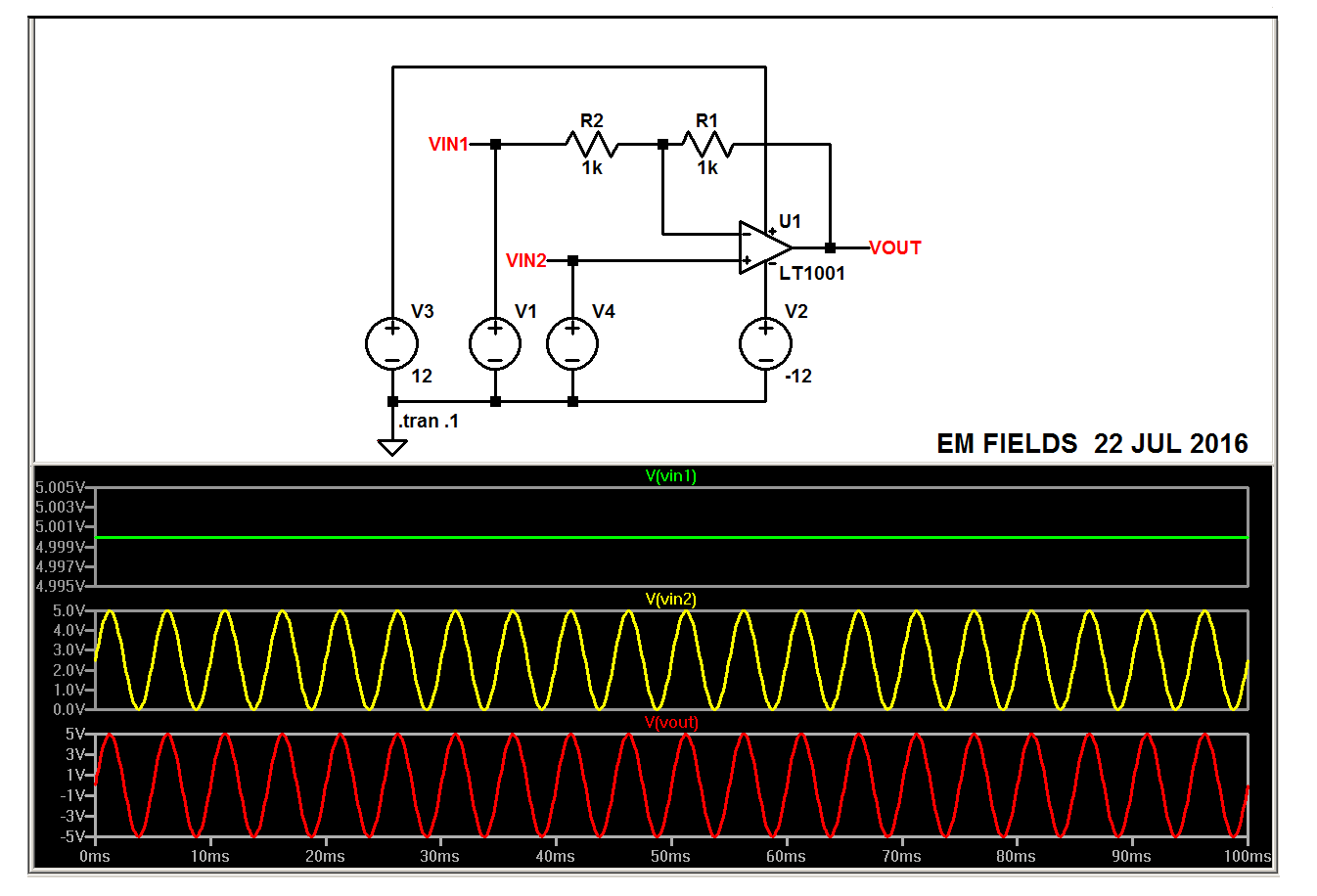
You asked" "Okay, so if we suppose Vin = 5V and Vin2 = 2V, and let's assume that I remove R2.. then according to the golden rules, V- has to be 2V so that the difference between the inputs is zero. In that case, as Vin2 varies from 0 to 5V, Vout will swing from -5V to 5V?"

Yes.

enter image description here

\$\endgroup\$
0
\$\begingroup\$

In the case of a difference amplifier, standard texts always show the non-inverting input connected to ground via a resistor (Rg). In that setup, Vout is trivial, but what about the setup shown below?

Ground is nominally half way between the most positive and most negative supply rails of the op-amp but it needn't be. If the rails are +/-5V then ground could be at +2V. The op-amp won't care.

So, the upshot of this answer is to regard the non-inverting input temporarily as mid-rail (or 0V or ground) and calculate the output based on numbers relative to that. When you have done this subtract that ground (or 0V) offset from the output.

\$\endgroup\$

Your Answer

By clicking “Post Your Answer”, you agree to our terms of service and acknowledge you have read our privacy policy.

Not the answer you're looking for? Browse other questions tagged or ask your own question.