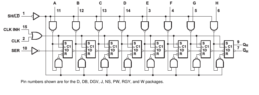
The classical approach here is to use some kind of IO extender IC. In the simplest case, this would simply be a parallel-to-serial-shift register, for example some variant of the 74xx165:

The picture is from the Texas Instruments SN74LV165A datasheet.
The idea is the following: When the SH pin is pulled low, the values at pins A-H are stored in the internal flipflops, so this is where you connect your switches/buttons that either connect the pin directly to supply voltage (if pressed, for example), or ground the pin throug a (largish) resistor:

simulate this circuit – Schematic created using CircuitLab
That way, when the button is pressed, the voltage at the input is "high", otherwise it's low. It's usually recommendable to connect a capacitor in parallel to the resistor, because that will counter so-called "bouncing". The actual resistor and capacitor values aren't critical – if you use a resistor value that's too small, you'll draw a lot of current with every button pressed, and if you choose a capacitor value too large, buttons will appear to take a long time until they are effectively pressed and released, but in general, something like 10kOhm and 10nF – 100nF, values abundant in most part boxes, should do well for human interaction.
Yet another hint: if you need to go shopping for parts, buy so-called resistor networks; for example, there's parts that contain 8 identical resistors that have one common pin (which you'd connect to ground here, and 8 individual pins. That way, you save yourself a lot of soldering work, and your circuit can look very clean and tidy.
Now, having pulled SH "high" again, the input values are stored in the flipflops.
Now your microcontroller would start to send a clock signal (high,low,high,low,…) to the CLK input. At every rising edge (i.e. low-to-high transition), an input value appears at QH, and the internal states are pushed one step "to the right", meaning that the second flipflop then contains the old value of the first, the third flipflop the old value of the second and so on. After six clock cycles, all the 8 input values have been sequentially shown on QH. That's why this shift register is usually also called a parallel to serial converting shift register.
You can actually daisy-chain those: if you take a second shift register and attach its QH to your shift register SER input, then the output values will be "concatenated" to your first shift registers values. That way, with only three pins on your Arduino (one pin driving SH, one pin driving CLK, and one pin reading the serial output from QH), you can have virtually unlimited amounts of buttons – and that at a unit price of less than 20ct per 8 inputs
The only limiting part is that you regularly have to pull down SH, pull it back up, and generate 8*(N_shiftregisters) clock cycles; this has to be done often enough not to miss a key press – but usually, with microcontrollers running at MHz's, and with SPI hardware that actually is meant for nothing different than talking to such shift registers, this isn't a problem at all – it's not uncommon to see someone query shift registers a couple thousand times per second.


