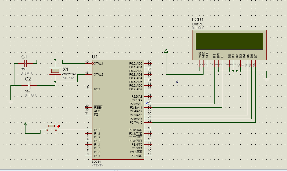
Apart from "typos" and untidiness in the code, the main issue appears to be that you assume that the input is a perfect on/off waveform. If the rising or falling input edges have "bounce" your code will see multiple inputs for bounce periods which are long compared to the loop time. As your loop time is at most in the microseconds range, and bouncing may occur over many milliseconds, you are 'lucky' to be seeing a maximum of only 3 counts per switch closure.
When mechanical switches open or close it is very common for them to not make a clean on/off or off/on transition, but for the contacts to literally 'bounce' mechanically so that a multiple off/on/off .... waveform is generated. The number of bounces is typically 'several' ie 2 or 3 or 4 or .... but if a particular switch managed 10's of bounces it would not be unexpected.
The usual way to deal with 'switch bounce' is to utilise a (no surprise) debounce system. This may be in hardware of software. In many cases it makes sense to do it in software as it is essentially "free" once implemented and can be adjusted if required for any reason.
Hardware debounce can be done by ensuring a somewhat slow/low frequency fultered signal line feeding a Schmitt triggered gate. The slowed rise of fall ensures that amy bounce transitions are reduced in amplitude and the Schmitt triggered input only accepts changes whoch are larger than the bounce signal amplitudes. A Schmitt trigger input with no input filtering may have the effect of ensuring that some bounces at least achieve rail to rail amplitudes when they originally were smaller.
Software debounce, which you can very easily achieve here, works by delaying acceptance of an input change until affects caused by bouncing have finished.
I'll use low to high changes below, but the method is essentially the same for high to low changes. Note that the characteristics of low-high and high-low changes may differ due to the circuitry used. In your example a high=low change is caused by a hard switch closure to Vdd so will be rapid as the node capacitance will be rapidly charged by the low resistance switch contact path. However, the high to low transitions, either from switch release OR from bounces while first operating the switch, will be slower as the pulldown resistor needs to discharge the pin capacitance. This difference may affect how switch closures and switch releases present bounce wise.
A simple method for low-high debouncing is to not accept an input which MAY still be debouncing. From observation or datasheet it may be known that bounces do not occur worst case mote than 5 ms after switch press. If a "1" is seen after a period of idleness then the switch MUST have been pressed. If you wait 10 ms (twice as long as worst case bounce here) and then process the "1" no bounces will be counted. This has the affect of delaying switch action - which may not be a problem, and of 'flying blind' - which also may not be a problem.
It may be known that bounces occur with not more than say 1 ms between them maximum BUT they may continue for 2 or 3 or ... perhaps sometimes 20 bounces. This can be overcome by testing for bounce every 2 ms and looping until no bounce is seen. This risks testing between bounces and being fooled. Better is to test continually for say 2 ms and starting again if a bounce is seen.
More complex schemes can be devised, and searching for "debounce" will find many examples, but the methods above will work well enough in many cases.
___________________________
Your IR input may or may not suffer from debounce issues. The ability to alter time constants or to switch the code off if desired is an advantage of using a "soft" solution.
___________________________
I am not sure whether the processor has an internal pull-down resistor on the input pin as configured. A pull-down resistor resistor, internal or external is required.
 In each rotation the the rotated number will be display on the LCD .

{}button!! Then, don't link to some discussion on a different forum. Make a reduced version of it and include it here. We're not going to read through all your posts just to understand what your problem is. Describe your system! The only thing you tell us is the processor family. That's really like going somewhere and telling your "flarb doesn't work", and then not telling them a "flarb" is actually car, or what's wrong with it. \$\endgroup\$