28
\$\begingroup\$

Disclaimer: I already know the solution of this circuit debugging conundrum (and it is not trivial), and I'll post it after some time, so that other people could give their contribution to this mystery story! I think it may have some educational value for circuit designers!

Some years ago (~8, IIRC) I stumbled upon a very interesting special offer at a local general store: some very nice (so I thought) Osram DOT-IT LED light appliances at half the price.

enter image description here

As you can see, they were small appliances, powered by three AAA batteries, encasing three very bright white LEDs. The whole thing was switched on through a soft switch actuated by pressing the transparent dome. At 1st press the three LEDs would turn on, and at every subsequent press one of the LEDs would turn off. So you could have the possibility to choose the amount of light the appliance would produce. The outer case, besides the transparent plastic dome, was very strong anodized aluminium, with the back cover being plastic with a strong magnet, which allowed to stick the thing to the fridge, the car body shop or whatever suitable metallic surface you might want.

Since at the time LED lighting was very expensive here in Italy, and small gadgets like those were either monstrously expensive or totally crappy, I thought it a very good idea to buy a dozen of them (I first tried with just one unit, and I verified it made very strong light and was of very high quality). I intended to use them as emergency lights in every room of my house and in my car.

All was fine until a brief black out happened after about 6 months. To my great disappointment, about 10 out of 12 of the things had their batteries dead!

Of course my first thought was "crappy leaky soft switch" and I ran for my micro-ammeter! Effectively I found a couple of units that had excessively high leakage currents (~1 mA), but the other ones had a quite honest ~20 μA. I was puzzled.

I replaced all the batteries in the low-leakage ones and decided to give them another try.

After a couple of months, surprise, they failed again! I measured the leakage again and got different results. Some units sported the terrible ~1 mA leakage, whereas the other were "normal". Moreover, I retested the two units which originally showed high leakage and... they didn't leak any longer!!!

I was fed off and since I had got no more time to waste on the issue back then, I scrapped them all, put them in a junk box (after all, they had three nice and expensive white LEDs in them, and I planned to salvage them) and forgot about them.

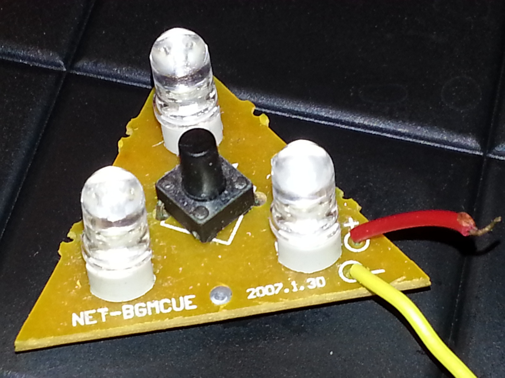
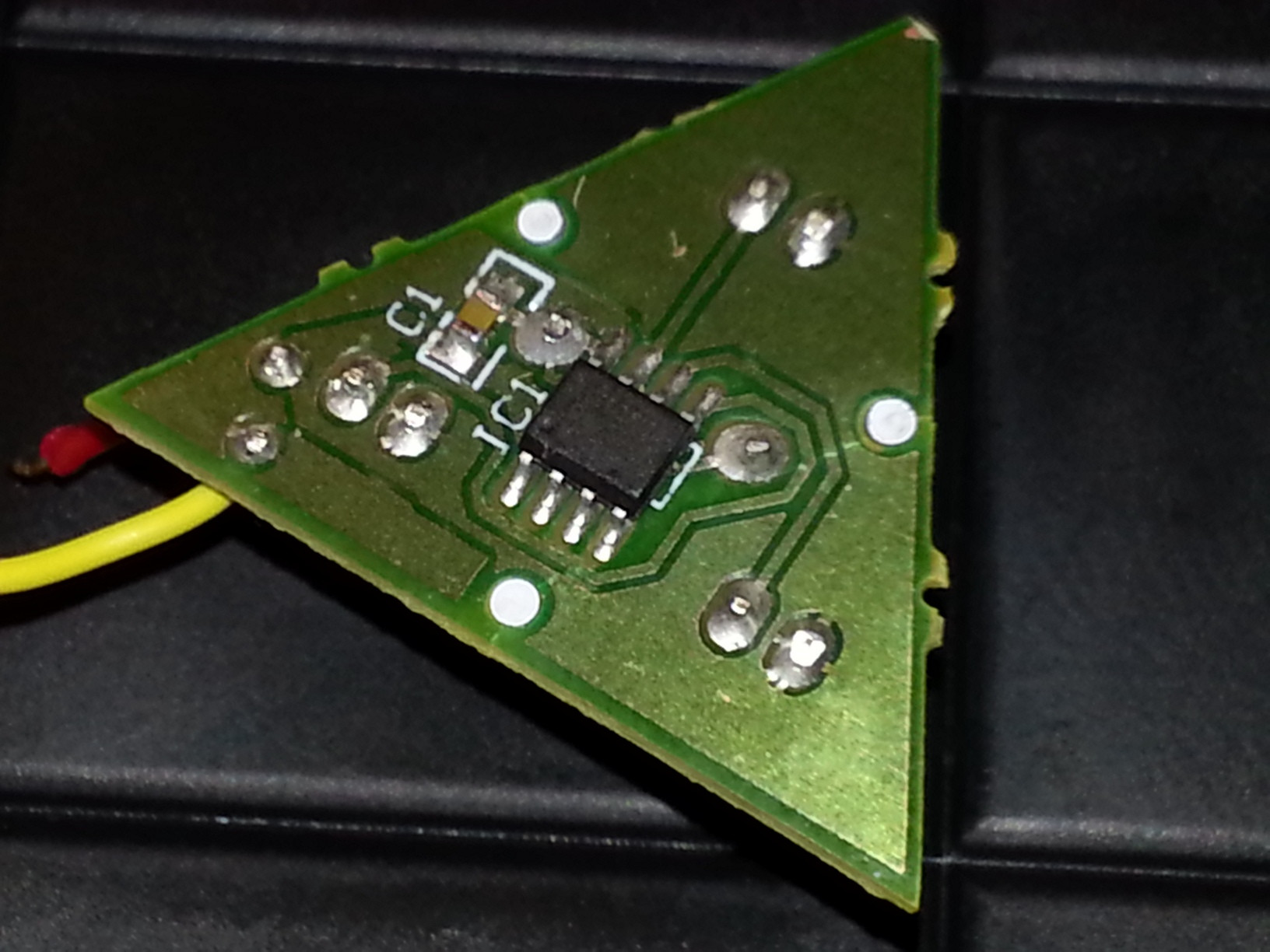
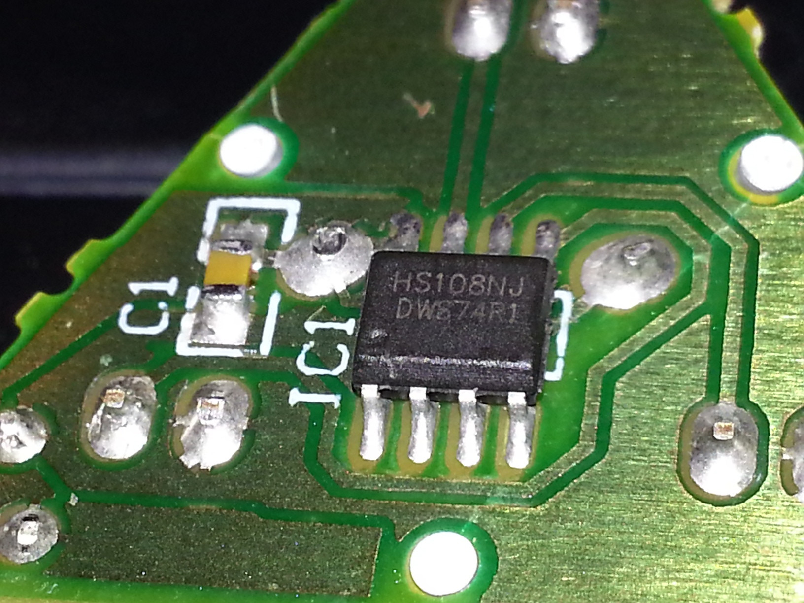
I found them again a couple of weeks ago and, in a reorganization frenzy, I thought to dismantle the units and salvage the LEDs. So I discovered that the internal circuitry was a tiny PCB holding just a momentary switch, the LEDs, a driver chip and a cap. The PCB is shown in the photos below (for curiosity I tried finding a datasheet for that driver chip, but with no luck).

enter image description here enter image description here enter image description here

I tested the PCBs again, just for fun, and I still got the erratic leakage behavior I had observed before, but in the process I finally discovered the culprit.

Guess what was the cause of that random and erratic leakage!

\$\endgroup\$
25
  • 1
    \$\begingroup\$ Whiskers (caused by incomplete etching) on the PCB, bridging traces? \$\endgroup\$ Commented Jul 29, 2016 at 19:57
  • 1
    \$\begingroup\$ RF pickup? Can we see the cause in any of the pictures? \$\endgroup\$
    – Neil_UK
    Commented Jul 29, 2016 at 20:04
  • 1
    \$\begingroup\$ @Neil_UK. The cause is not really in the photos. As for RF pickup..., it is not the culprit. But you are coming a little closer...! \$\endgroup\$ Commented Jul 29, 2016 at 20:06
  • 6
    \$\begingroup\$ +1 for a interesting question, but also because of pictures that were relevant, properly focused, and with the right crop to show what is needed but leave out what is not needed. This would be a good question to refer to for how to properly post pictures of circuits. \$\endgroup\$ Commented Jul 29, 2016 at 20:34
  • 5
    \$\begingroup\$ Incident light on the LEDs? \$\endgroup\$
    – John D
    Commented Jul 29, 2016 at 20:35

3 Answers 3

15
\$\begingroup\$

I suspect something to do with the strong magnet (I wouldn't have suspected it, except that it must be an interesting answer or you wouldn't have posed the question). Perhaps having the magnetic field induces a current in a loop somewhere. Was the leakage higher when there was more area between the wires connecting to the battery? Or it could be a current in some other loop.

\$\endgroup\$
15
  • 1
    \$\begingroup\$ Wow! We have a winner here! :-) \$\endgroup\$ Commented Jul 29, 2016 at 20:29
  • 4
    \$\begingroup\$ As I understand it, it's a permanent magnet mounted on the unit in the same position relative to the electronics. This therefore couldn't induce any voltage or current since the magnetic field doesn't change at the electronics. Even if the magnet is moved as part of replacing the batteries, it would presumably be in a fixed location during the initial test after replacing the batteries and re-assembling the unit. \$\endgroup\$ Commented Jul 29, 2016 at 20:30
  • \$\begingroup\$ I'll post an answer for the details, but you surely deserve the acceptance mark (also for your detective skills!). \$\endgroup\$ Commented Jul 29, 2016 at 20:30
  • 1
    \$\begingroup\$ Some weird Hall effect internal to the chip? Normally this would only be a problem if a current was actually flowing. Perhaps on first assembly everything would be fine as no current was flowing but when the button was pressed current flows and a Hall voltage causes a latch-up inside. \$\endgroup\$
    – Transistor
    Commented Jul 29, 2016 at 20:35
  • 3
    \$\begingroup\$ @Lorenzo: Moving magnetic things near a permanent magnet does change the magnetic field. The derivative of the field should still be quite small, particularly on the other side of the magnet, but it would be non-zero. A least it's not impossible for this to be a cause, but the effect should be very weak. The Hall effect is more likely, since it works on the instantaneous magnitude of the field. Perhaps as Transistor said, this caused strange voltages in the chip when current flowed, which could possibly cause some strange latching. \$\endgroup\$ Commented Jul 29, 2016 at 20:41
15
\$\begingroup\$

Here is the summary of my investigations and my findings on the mysterious case of the random leakage current.


When I began dismantling the units, I also got curious and wanted to research a rational cause for that odd behavior. I had no luck until I almost inadvertently moved the magnet near a powered-up PCB. The ammeter jumped to about 2mA and stabilized at a slightly lower value.

At first I thought it was just a mechanical effect due to my handling of the PCB, but after repeated tests I verified that there was a clear correlation between moving the magnet near the PCB and having that sort of "latch-up".

It wasn't sure-fire, though, because it depended in an unclear way on the magnet orientation and the direction of the movement and also on the speed with which I moved the magnet.

I couldn't assess the real mechanism, but the cause was clear. The interaction of the PCB (and most probably the driver chip) with the moving magnet.

I also verified that the latch-up could happen when moving an assembled unit near a massive ferromagnetic body, such as when attaching the unit to a fridge. But the phenomenon in this case was less repeatable and more erratic.

The options that came to my mind were obviously two:

  • induced current generated by the variation of magnetic flux linked with some loop
  • Hall effect disturbing the normal behavior of some semiconductor components inside the driver chip

I cannot say for sure which is the real culprit between those two. I leave the final decision to the experts on EE.SE who are more knowledgeable than I am on such topics.

I cannot be sure, but I suspect that whoever was in charge to test the prototype didn't perform proper testing when the magnet was in place. In fact the magnet wasn't built-in in the back cover of the units, but was provided as an add-on in the package. You had the option to stick it to the back cover since one side of the magnet was adhesive.


I hope you enjoyed this little mind-teaser, vaguely inspired to Sir Arthur Conan-Doyle's novels.

\$\endgroup\$
1
  • 9
    \$\begingroup\$ "When recording data, if you see something that looks funny, record the amount of 'funny' ". Tom Milligan as quoted by Bob Pease \$\endgroup\$ Commented Jul 30, 2016 at 9:19
7
\$\begingroup\$

This kind of symptom smells of missing pulldown (or pullup, depending on topology) resistor on a FET gate. All is fine if the system powers up without the startup transient activating the FET. If that is successful, all is well. If not, the system latches into some wierd state that manages to draw some current.

I notice this is a single-sided board. That means thru-hole leads are only held by the solder meniscus on one side of the board, not inside the plated hole and on both sides like on a two layer board. After enough mechanical stress or thermal cycling, such solder joints can get flaky. This can be very hard to see, even with a jewler's loupe. I've personally seen such a board fail in seemingly random ways, and visual inspection didn't reveal the problem, even though I was looking for bad solder joints. Reflowing every joint and adding additional solder fixed the problem.

Another cause for such symptoms is that the button is pressed all the time. However, I'm figuring this isn't the case because then the lights wouldn't have worked in the first place. That kind of pushbutton has a positive click feel. The only way this problem could happen in your circumstance is if the button worked right for the first three clicks, then got stuck on with the click that turned the light off. It is unlikely that so many units would work fine for three clicks, then all get stuck on the forth, so I'm not thinking this is the problem.

I can think of scenarios where a badly designed circuit can latch into a unintended state with the power supply glitching and bouncing as the batteries are installed, possibly depending on whether the button was pressed or not at the time. However, all these scenarios would leave the unit obviously inoperative immediately. I'm assuming that you tested each unit thru at least one cycle of ON-OFF before declaring it ready and sticking it on a wall or whatever.

\$\endgroup\$
2
  • \$\begingroup\$ Interesting theory! I cannot comment on the quality of the PCB build, so it may have eventually developed some problems because of what you point out, but it wasn't the culprit! \$\endgroup\$ Commented Jul 29, 2016 at 20:10
  • \$\begingroup\$ BTW, I only discovered the cause, not the actual mechanism. Effectively, some kind of latch-up might have been involved in the mechanism, but the cause was not mechanical stress or bad solder joints. \$\endgroup\$ Commented Jul 29, 2016 at 20:13

Your Answer

By clicking “Post Your Answer”, you agree to our terms of service and acknowledge you have read our privacy policy.

Not the answer you're looking for? Browse other questions tagged or ask your own question.