0
\$\begingroup\$

Why don't Circuit 1 and 2 work?

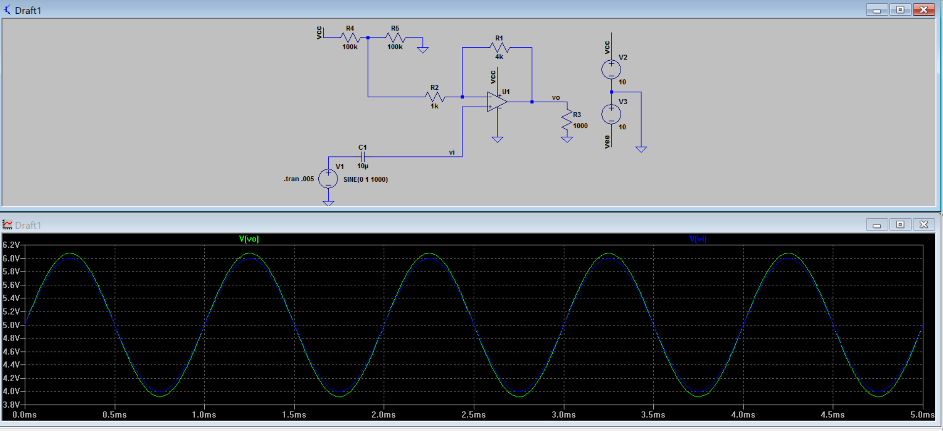
Circuit 1: enter image description here I don't get gain of 4 but of about 1 like buffer amplifier.
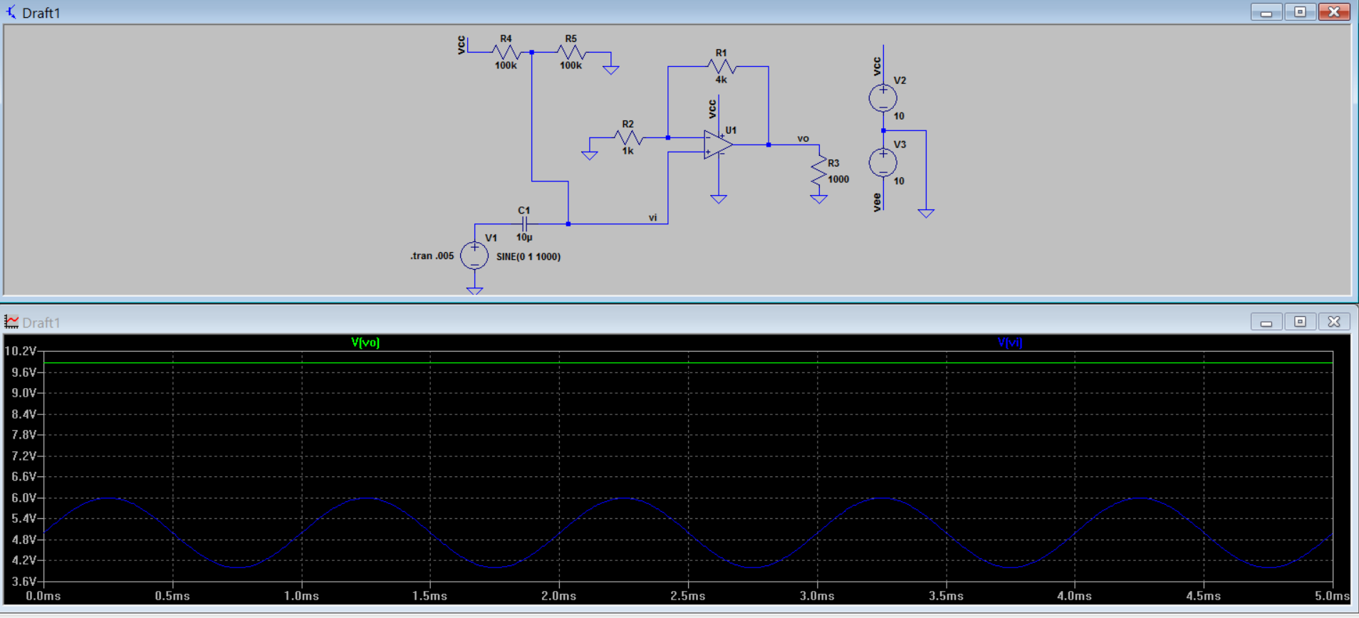
Circuit 2, I just connected R2 to ground and the Vcc/2 generated using R4 and R5 to noninverting input of opamp: enter image description here More mysterious; here the opamp is stuck at vcc.
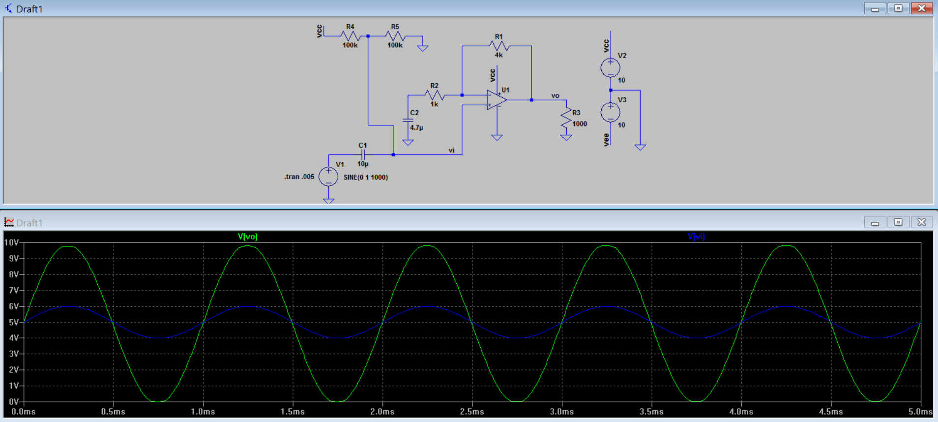
Circuit 3, similar to circuit 2 but now there is a capacitor between R2 and system ground: enter image description here This one works.
EDIT:

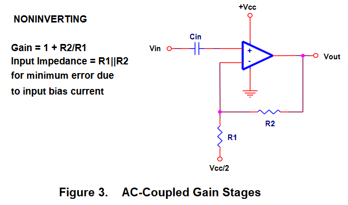
OK, thanks for the answers. I want to reach a conclusion now. I conclude that the following circuit from SLOA058 page 6 is wrong:

enter image description here

Since I use a voltage divider to created Vcc/2, this circuit simply will not work. Do you agree? It seems that this application note has wasted a lot of my time.

\$\endgroup\$
3
  • \$\begingroup\$ You have two completely separate questions. It would be better if you ask them separately. The frequency response due to C1 and C2 has nothing to do with any reasons for your first circuits' functionality. \$\endgroup\$
    – pipe
    Commented Aug 2, 2016 at 18:25
  • \$\begingroup\$ I have made the edit \$\endgroup\$
    – quantum231
    Commented Aug 2, 2016 at 18:30
  • 1
    \$\begingroup\$ Please, post the schematics as separate, adequately cropped images. As they are now it is very difficult to see the circuit details without enlarging the pics, which is very annoying, especially because the circuits are simple enough to be shown entirely in decently sized pictures. \$\endgroup\$ Commented Aug 2, 2016 at 18:51

3 Answers 3

4
\$\begingroup\$

Circuit 1 doesn't work mostly because your 100k pair voltage divider is not appropriate to set a bias point for the inverting (-) feedback network.
The currents flowing through the 4k & 1k will easily pull that so-called voltage divider waaay off where you thought it would be and this is what gives you a gain of approximately 1.1
Also, your input to the non-inverting (+) input of your opamp has no DC bias set - it depends entirely on the opamp's biasing/leakage currents.

Circuit 2 doesn't work because you're applying a DC bias to your non-inverting input (good), but then amplifying it by the gain of your opamp circuit (bad). So your opamp is trying to drive its output to 25V, but it only has a 10V supply.

Circuit 3 works because you've separated the DC gain from the AC gain by adding that capacitor.
This circuit has an AC gain of 5, but a DC gain of only 1, so your input signal appears on the output amplified by 5 and riding on a 5V DC level.

\$\endgroup\$
8
  • \$\begingroup\$ aha, so the DC bias voltage was getting amplified... hmm I see \$\endgroup\$
    – quantum231
    Commented Aug 2, 2016 at 19:59
  • \$\begingroup\$ If I want to link multiple single supply opamp stages, do I need to have decoupling capacitors between each of them together with a voltage divider to biast the input? \$\endgroup\$
    – quantum231
    Commented Aug 2, 2016 at 20:52
  • 1
    \$\begingroup\$ Not really. If the bias voltage you add at the input of the 1st stage stays unamplified (and reasonably unchanged due to opamp offset errors) then as long as you continue to ensure that the DC gain of your stages is 1 you can stack them without AC coupling and re-biasing each one. \$\endgroup\$
    – brhans
    Commented Aug 2, 2016 at 21:12
  • \$\begingroup\$ ok, that is done. I got the results from simulation as you stated. I am feeling much at ease now. The one issue that remains is a circuit in the application note SLOA058 that I think is wrong. I have edited the question. I will be very thankful for your comment related to it. \$\endgroup\$
    – quantum231
    Commented Aug 2, 2016 at 21:59
  • 1
    \$\begingroup\$ @quantum231 It's almost literally the first thing they discuss, and section 1.2 in SLOA058 shows the circuit they use to generate a stable VCC/2. You can see that it is indeed buffered. \$\endgroup\$
    – pipe
    Commented Aug 2, 2016 at 22:54
2
\$\begingroup\$

First circuit: There is no DC bias path for the (+) input.

Second circuit: The (+) input is biased to +5v, the feedback is amplifying with a gain of 5 from ground. 5 * 5 = 25, which is greater than 10, so the output is pegged to the rail.

Measure DC before worrying about any any signals!

See also Single Supply Audio Amplifier

Edit: This figure 3 circuit is wrong because there is no DC bias to the (+) input, not because of anything with the voltage divider.

\$\endgroup\$
1
\$\begingroup\$

I'm not sure what the problem with Circuit 2 is, but the problem with Circuit 1 is clear.

Circuit 1 doesn't work because the dual 100 kΩ divider you're using to try and bias the op-amp's +IN to ½Vcc is also half in series with the ground leg of the feedback divider, so that the gain isn't calculated as 4 kΩ ÷ 1 kΩ + 1 = 5 (not 4!) but as 4 kΩ ÷ (1 kΩ + 100 kΩ) + 1 ≈ 1.

The virtual ground biasing trick you're attempting to use only works with the inverting op-amp configuration.

\$\endgroup\$

Your Answer

By clicking “Post Your Answer”, you agree to our terms of service and acknowledge you have read our privacy policy.

Not the answer you're looking for? Browse other questions tagged or ask your own question.