1
\$\begingroup\$

What I'm essentially trying to do is to add an amplifier to a simple passive radio receiver:
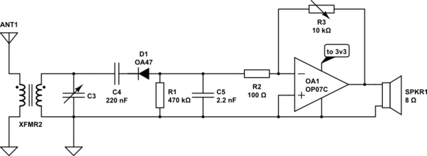
schematic

simulate this circuit – Schematic created using CircuitLab

XFMR2 consists of two inductors 0.4 uH and 730 uH. C3 varies between 35 and 235 pF (or something like this). Numbers and the whole left part is taken from here.

The idea is to demodulate negative part of a signal via D1, R1, C5 and pass it to an inverting amplifier based on OA1.

If this circuit is going to work: I'm interested in receiving medium frequencies. It is said they're quite tough to receive in a city due to industrial and home EM noise, especially during days. Am I going to need something more sophisticated instead of this circuit? (not going into antenna discussion here)

Also, why germanium diode OA47? Can I replace it with a Schottky diode?

\$\endgroup\$
1
  • 2
    \$\begingroup\$ You're running the OP07C at half the minimum recommended supply voltage. It has absolutely no headroom left. It's designed for ±15 volts. \$\endgroup\$
    – pipe
    Commented Aug 11, 2016 at 0:32

1 Answer 1

5
\$\begingroup\$

It wont work .C4 stops the detector diode from working .Remove C4 by shorting it .R2 is way way to low and will load the tuned circuit meaning no selectivity.Use a high impedence buffer like say a MPF102 or an opamp to keep some selectivity.Your audio output stage looks iffy so recheck the biasing .The Ge diode is slightly better than the Schotty here.

\$\endgroup\$
1
  • 2
    \$\begingroup\$ I would move C4 to before the opamp and add a bit of bias after it to get near the middle of your OP drive range. Selecting a low voltage (many modern devices) amp is critical and everything @Autistic said. \$\endgroup\$
    – KalleMP
    Commented Aug 11, 2016 at 7:09

Your Answer

By clicking “Post Your Answer”, you agree to our terms of service and acknowledge you have read our privacy policy.

Not the answer you're looking for? Browse other questions tagged or ask your own question.