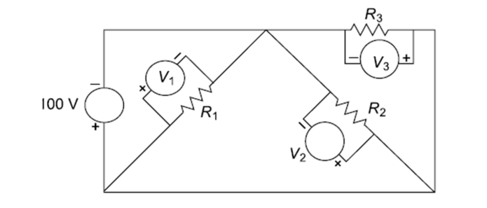
This is actually (as you have noticed, with a face-palm) a trick question. It's designed to see how observant you are.
The circuit is laid out in such a way as to trick you into thinking it's more complex than it is. It isn't though - it can be better drawn out like this:

simulate this circuit – Schematic created using CircuitLab
You notice I have also turned the schematic upside down so + is at the top and - is at the bottom. You can now instantly see that the three resistors are just all in parallel with each other and therefore all in parallel with the 100V supply, making the voltage across each resistor 100V.
You have to remember that in a schematic all the nodes and "joins" that are linked together by a simple wire are effectively the same node. In the schematic above I have coloured a selection of wires in red. They are all the same wire - all the same node - and thus all at the same potential. It's only when you come to tracing the current flow through it that you start to split values between different branches.
So, \$V_{M1} = V_{M2} = V_{M3} = V_1\$ and \$I_{R1} = \frac{V_1}{R_1}, I_{R2} = \frac{V_1}{R_2}, I_{R3} = \frac{V_1}{R_3}\$


