2
\$\begingroup\$

I'm using a Raspberry Pi connected to a custom breakout board. I'm reading in low power signals from an analog opto-isolator and was wondering if there are any specifications for the GPIO pins such as \$V_{IH}, V_{IL}, I_L\$? I'm trying to get the most gain I can from the isolator without adding additional hardware, which means having a large value pull-up resistor.
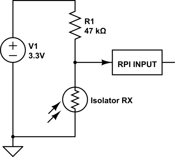
schematic

simulate this circuit – Schematic created using CircuitLab

I have found for the PI it seems documentation is sparse...

If there is no documentation that anyone knows of, would the illustrated method below be considered reasonable for \$\pm\$5% measurements? I would take the measurement over a few temperature ranges (~0C, ~20C, ~40C).
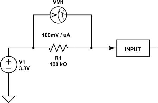

schematic

simulate this circuit

\$\endgroup\$
4
  • \$\begingroup\$ I guess \$V_{IL}\$ and \$V_{IH}\$ are most likely \$0.3V_{CC}\$ and \$0.6V_{CC}\$ respectively. Current is mostly irrelevant for an input - it is high impedance. \$\endgroup\$
    – Majenko
    Commented Aug 18, 2016 at 21:32
  • 1
    \$\begingroup\$ Yes but I'm feeding the input with a source that could be around 47k to 100k Ohm, so it is no longer irrelevant. I am trying to avoid adding a buffer amplifier to save space... \$\endgroup\$
    – MadHatter
    Commented Aug 18, 2016 at 21:33
  • 1
    \$\begingroup\$ Reading between the lines, I suspect that you are trying to make an analog measurement using the Pi's digital GPIO pins. As far as I know, the Pis do not have any analog inputs, so you can't do analog meaurements with them (without adding an external ADC). \$\endgroup\$ Commented Aug 19, 2016 at 0:37
  • \$\begingroup\$ Peter Bennett, I am reading a digital signal, but the signal has a very weak drive. I am concerned with input leakage current. \$\endgroup\$
    – MadHatter
    Commented Aug 19, 2016 at 15:28

2 Answers 2

1
\$\begingroup\$

CMOS digital inputs are normally specified in terms of leakage current, rather than input impedance. I can't find anything specific to the pi, but normal values are around 1uA.

1uA*100kOhm = 0.1 volt, which is a small but potentially significant value. If possible, you'd want to measure the leakage current of the pi and choose a resistor accordingly. Your setup seems like a reasonable idea.

As a side note, the pi's inputs have an input pull up enabled by default on them (last time I was using one, anyways). Make sure you turn it off!

\$\endgroup\$
1
  • \$\begingroup\$ Thank you for atleast understanding what I was asking. I'm surprised by the number of people that didn't understand, I thought it was clear... I guess I should have specifically said input leakage. \$\endgroup\$
    – MadHatter
    Commented Aug 19, 2016 at 15:30
-2
\$\begingroup\$

As long as you are configuring the GPIO as an INPUT, the current (as Majenko pointed out) should be irrelevant. I found this article that seems to have a good explanation of the RPi GPIOs. Take a look at the schematic for a GPIO. There is no current path when you have the GPIO configured as an input and you turn off the internal pull-up and pull-down.

Your comments suggests that you are worried about the current that the opto-isolator can provide. In that case, you just need to be sure that it can sink 3.3V/47kOhm ~= 70uA of current for the signal you are trying to measure. Otherwise you will have a signal swing of something less than 3.3V.

\$\endgroup\$
3
  • 1
    \$\begingroup\$ -1, because with a high impedance input, the leakage/input impedance can start to have a significant effect. \$\endgroup\$
    – mbrig
    Commented Aug 18, 2016 at 23:02
  • \$\begingroup\$ @mbrig I am curious where you got a 1uA leakage number from. When I read the OP question, input leakage wasn't even on my radar because I have never seen such a high number quoted or specified. Certainly no CMOS input will have anywhere close to that much leakage \$\endgroup\$
    – Daniel V
    Commented Aug 21, 2016 at 6:40
  • \$\begingroup\$ 1uA max leakage is the spec'd number for a lot of the atmel chips (like the 328p). A random TI cortex m4 I looked at was max 0.4uA (on fast gpio), and max 4nA on slow gpio. The number is probably lower in practice, but presumably you can reach those in a worst case. \$\endgroup\$
    – mbrig
    Commented Aug 21, 2016 at 6:59

Your Answer

By clicking “Post Your Answer”, you agree to our terms of service and acknowledge you have read our privacy policy.

Not the answer you're looking for? Browse other questions tagged or ask your own question.