0
\$\begingroup\$

I'm trying to get into conponent level board repair, and to do so I need to have a good understanding of electronic symbols. I've been trying to find a pdf that would explain all the symbols I see on a schematic but, unfortunately, I've found nothing. I'm hoping that somebody could reommend a site or a pdf or something for me that would include ALL the symbols I might come across. Thank you very much in advance!

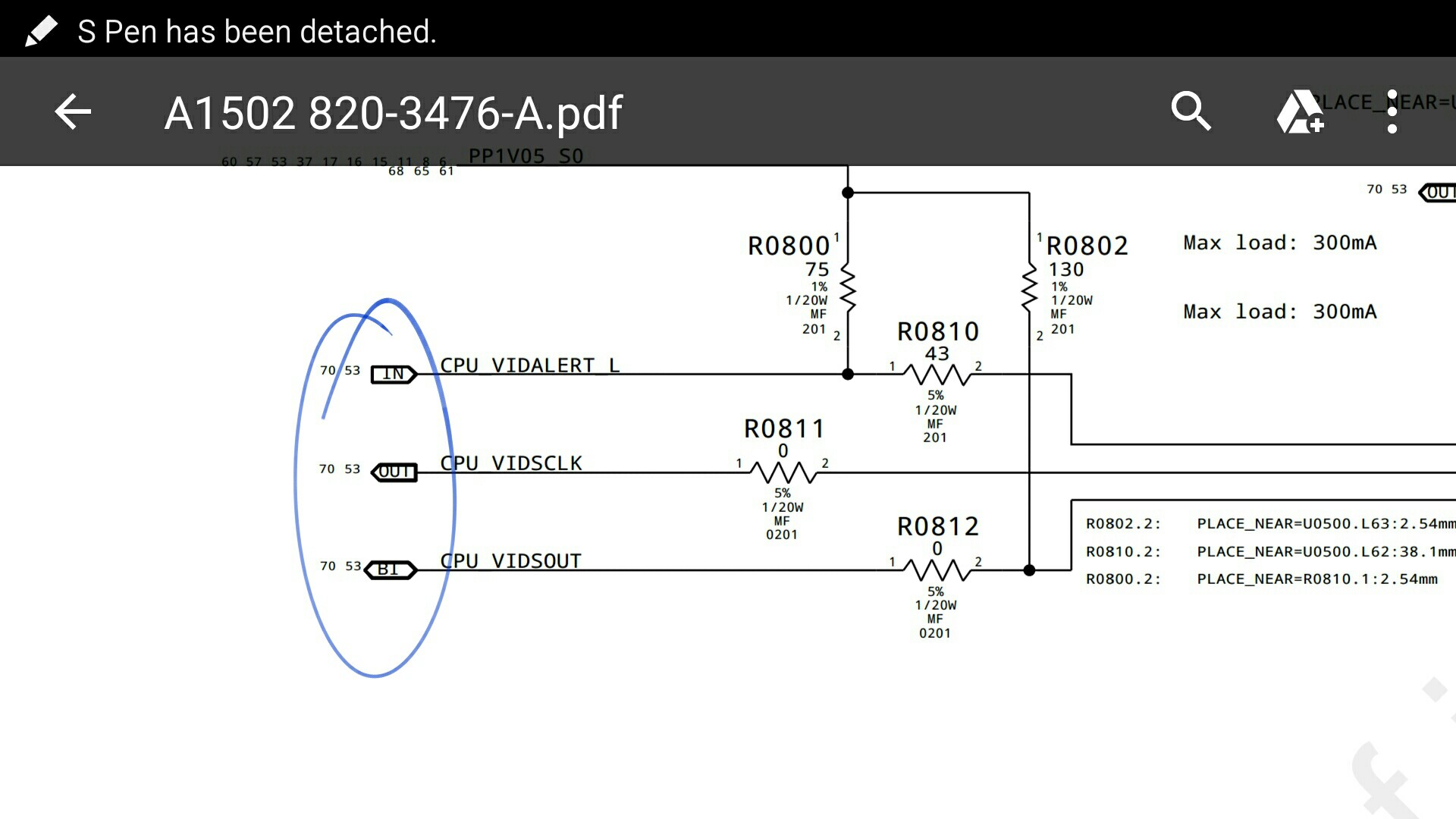
Also, if anybody could explain to me what the circled symbols in the image attached mean, that would be really helpful as well. These were the symbols I originally started seaching for...

Symbols I couldn't find the meaning of

\$\endgroup\$

2 Answers 2

3
\$\begingroup\$

There is no comprehensive collection of ALL schematic symbols because there is no single "standard" for what symbols to use or for what they mean. Most are made up as we go along and need new symbols for new things, or as understanding and formal organization of knowledge of circuit design and function evolves. Certainly if you are limiting yourself to a single designer/manufacturer (such as Apple, etc.) then they likely have a "house standard" for schematic symbols which you can come to understand by simple familiarity.

The symbols you are asking about are generally known as "off-sheet connectors" (at least that is what I call them). They indicate that the signals go to some other board, or some other page of the schematic diagram collection of pages.

In many cases, the shape is arbitrary and has no intrinsic meaning. But in your specific example, note that the shape of the "arrow" indicates whether the signal is coming "in" to the page, or going "out" of the page. Or in the case of your example, the connections are clearly labled as "IN" and "OUT" and "BI" which means bi-directional (both in and out). And in your example the numbers at the outside of the symbols likely are references to where you can find the other end of the symbolic "connection".

\$\endgroup\$
0
\$\begingroup\$

Connections to other matching "functional names" usually are to reduce clutter in long paths in schematics and in this example are enclosed in a box which indicate direction of destination. Each company may choose their own "standard" here.

The small numbers here is just one method to indicate the schematic pages where used for that name, depends on complexity and drafting practice. Sometimes a matrix code for edge rows and columns marked on the sheet are used to show the destination of the signal on a page.

In modular functions like a Consumer TV, the Function of that section and the Reference Designations are assigned 100 block numbers so that Cxxx and Rxxx coincide with the Module xxx for easy finding and are located together on the board.

\$\endgroup\$

Your Answer

By clicking “Post Your Answer”, you agree to our terms of service and acknowledge you have read our privacy policy.

Not the answer you're looking for? Browse other questions tagged or ask your own question.