0
\$\begingroup\$

I have created a bandpass filter with an LMC660CN chip, as shown in the image below.

However, in regards to just the high pass filter section, the filter's AC response is set so that at Vout a high pass filter is created with 1 kHz as the filter cutoff point, and it then has unity gain set by RF and RG. I also coupled RG to a 2.5 V voltage reference, in hopes that the output would oscillate about 2.5 V. That has not happened.

V1 in the schematic is a simple piezo disc in a black plastic case. It is AC coupled to the + input of the LMC660.

When the piezo is "at rest", the filter gives no output. When the piezo is slightly stimulated by the water pipe it is resting on, and vibrates at about 2.5 kHz, the filter begins to oscillate at about 20 Hz, and on each oscillation it reaches the positive power rail, 5 V. Also, this filter oscillation is also detected in the signal line of the piezo, probably from the + input interacting with the op amp's output.

Can anyone suggest why the filter begins to self-oscillate when the piezo creates a 100 mVpp at the + input? I am wondering now if it is connected to RG being coupled to VREF.

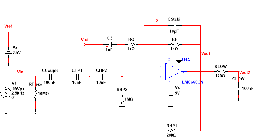
LMC660CN high pass and low pass filter

Gain vs. Frequency for high pass filter at Vout

Phase response for my filter's output at Vout

\$\endgroup\$
9
  • \$\begingroup\$ It seems to be a compensation problem of op-amp, try to get frequency response of the system. And check out phase/gain margins. \$\endgroup\$
    – MimSaad
    Commented Sep 10, 2016 at 16:40
  • \$\begingroup\$ @Mimsaad -- Looking at the phase margins, at about 2.5 kHz, which is the main frequency of vibration for the piezo, I see the phase response is about 0 degrees, which I understand as being the same as 360 degrees, and the gain at that point is about 1. This to me sounds like the criterion for creating an oscillator, (except having the gain a little more than 1). Do you think this phase being 0 degrees near my main vibrating frequencies to be the main cause of this oscillation? \$\endgroup\$ Commented Sep 10, 2016 at 16:49
  • \$\begingroup\$ Great, please add those information to your question. By the way, What is the frequency of undesired oscillation? \$\endgroup\$
    – MimSaad
    Commented Sep 10, 2016 at 16:56
  • 2
    \$\begingroup\$ Get the simulator to show you the Q factor of the circuit; high Q factors have an impulse response that can cause long term (relative to the signal of interest) ringing or damped oscillations. \$\endgroup\$ Commented Sep 10, 2016 at 17:03
  • 1
    \$\begingroup\$ If you want the output to be centered on Vref, then resistor RHP2 should go between the +input and Vref (rather than GND). \$\endgroup\$
    – davidcary
    Commented Sep 10, 2016 at 18:43

1 Answer 1

2
\$\begingroup\$

For equal value capacitors (which you very nearly have) the Q is: -

Q = \$\dfrac{1}{2}\sqrt{\dfrac{1Mohm}{20kohm}}\$.

By my calculations that is a Q of 3.53 and just a little too high for the sallen key topology given that you have also got gain in the pass band. It will oscillate.

\$\endgroup\$
1
  • \$\begingroup\$ Just to start, I lowered RHP2 to 10 kohms, to get a Q = 0.35 and the filter has stopped oscillating. \$\endgroup\$ Commented Sep 10, 2016 at 17:50

Your Answer

By clicking “Post Your Answer”, you agree to our terms of service and acknowledge you have read our privacy policy.

Not the answer you're looking for? Browse other questions tagged or ask your own question.