0
\$\begingroup\$

I'm doing some experimenting with a 2N6388 Darlington Transistor, and getting some unexpected (to me) results. It's been a while since I've played with a raw transistor, so there's a very real possibility that I'm simply mis-remembering how these things work.

According to the datasheet (last page), pin 1 is the base, 2 the collector, and 3 is the emitter.

However, when I apply 5V to pin 1 (base), 12V to pin 2 (collector), and pull down pin 3 with a 100K resistor, I read ~5V on pin 3, where I think I should see 12V.
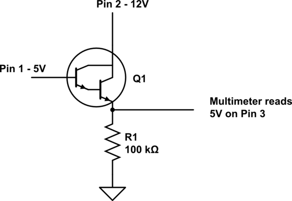
schematic

simulate this circuit – Schematic created using CircuitLab

If ignore the datasheet and treat pin 1 as the collector and pin 2 as the base, and swap the voltages accordingly, then I finally see the 12V on pin 3, and can turn it on and off by alternating pin 2 between 5V and GND.

So, is the datasheet wrong (I doubt it), or do I had a counterfeit transistor (kinda doubt that, too), or (most likely) am I making some fundamental mistake that's leading me astray?

Thanks

\$\endgroup\$
2
  • \$\begingroup\$ What do you exactly mean with "connected to 5V" ? Which kind of source? uP port? power supply? current limited? powering something else at the same time? \$\endgroup\$
    – carloc
    Commented Sep 11, 2016 at 18:24
  • 2
    \$\begingroup\$ where I think I should see 12V. Then you do not understand how transistors operate. For it to conduct (which is what you want) there needs to be a positive voltage between Base and Emitter, for a Darlington BJT like this on, about 1 - 1.2 Volts. With 12 Volts on the emitter like you want Vbe would be -7 V so a negative voltage, then an NPN like this one will never conduct. \$\endgroup\$ Commented Sep 11, 2016 at 18:54

4 Answers 4

5
\$\begingroup\$

If your drawing above is correct, I'd expect to see about 4 volts at the emitter with 5 volts on the base. The circuit is an emitter follower, so the emitter voltage should be about two Vbe drops below the base voltage.

The 100K emitter resistor likely does not draw enough current to produce the full Vbe drops in the transistor. You might try 1K or so as an emitter resistor for a more realistic base-emitter voltage drop.

\$\endgroup\$
5
\$\begingroup\$

Look at page 2 of the data sheet, where it says "Cutoff current". You'll see that with no base input at all, for 60 volts emitter-collector you might see as much as 1 mA. Now, it's true that you're not putting 60 volts across it, but 5 volts into 100k is only 50 uA, so you don't need 60 volts to get the sort of current you're seeing.

You might try simply letting the base float, and I suspect you'll see more than 5 volts on the emitter. Your circuit is being driven by leakage, not signal.

\$\endgroup\$
2
\$\begingroup\$

Many darlingtons have internal resistors of surprisingly low value (<<100k) shunting the base to emitter to keep them turned off against leakage. The base voltage might be simply getting onto the emitter resistor via these resistors.

I was surprised when I read the data sheet for that device, 8k and 120 ohms for the first and second BE junctions!

\$\endgroup\$
1
\$\begingroup\$

Iceo = 1mA max at 60V your load is 0.05uA @5V which suggests you are running in Vbe=0 cutoff mode, when Iceo is measured.

\$\endgroup\$

Your Answer

By clicking “Post Your Answer”, you agree to our terms of service and acknowledge you have read our privacy policy.

Not the answer you're looking for? Browse other questions tagged or ask your own question.