Problem
I am driving an inductive load from a microcontroller using a MOSFET. I have a current sense resistor in series with the load. I don't have much experience with transistors (should have paid more attention in school!) so I'm trying to implement the circuit using both an NMOS and PMOS transistor.
The problem is that the PMOS circuit is behaving as expected while the NMOS circuit is behaving erratically. I would like to know what is causing the differences.
P-Channel MOSFET
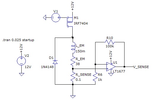
Here is the circuit with the P-Channel MOSFET. V1 is a 32 kHz PWM signal with 50% duty cycle. Since the current sense resistor is connected to ground, I can easily measure the voltage using a non-inverting amplifier.
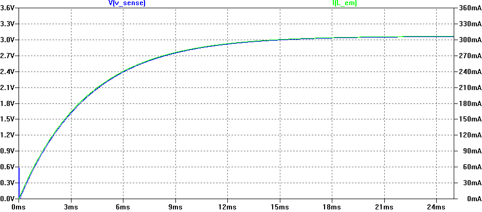
As the simulation results, the circuit does exactly what you expect; the voltage across the current-sense resistor tracks perfectly linearly with current in the inductor.
N-Channel MOSFET
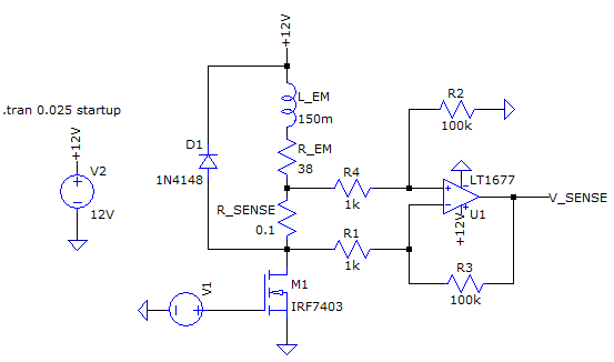
Here is the circuit with the N-Channel MOSFET. V1 is a 32 kHz PWM signal with 50% duty cycle. The current sense resistor isn't connected to ground so I use a differential amplifier to measure the voltage across it.
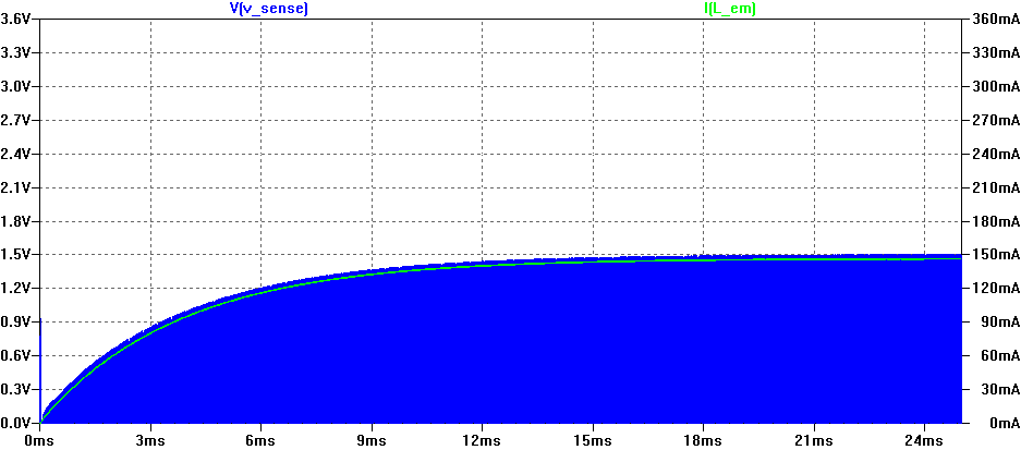
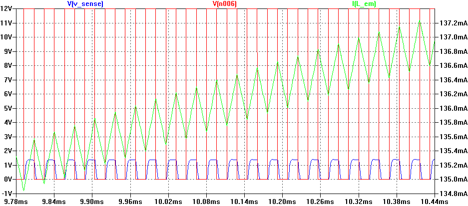
The behavior of this circuit is not what I expect it to be. The current through the inductor is much lower than the PMOS topology and V_SENSE is a mess.
Here is a zoomed in version with the PWM signal V1 included (shown in RED).
Questions
Why is the current through the inductor in the NMOS circuit half that of the PMOS circuit?EDIT: Fixed schematic, swapped PMOS drain & source- Why is the differential amplifier not working as expected? I am guessing that R2 is somehow coupling the op-amp inputs to ground. Since R_SENSE is "floating", this is causing issues.
You can't tell from my graphs but in the NMOS circuit, the current through the inductor is much noisier than the PMOS circuit.EDIT: Fixed schematic, swapped PMOS drain & source

