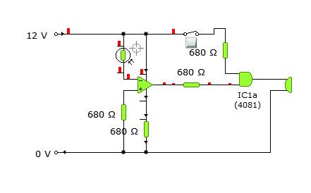
First of all, you cannot ever leave gate inputs floating (not connected to anything). This may be OK in a simulation, but it may cause all sorts of problems if you try to build this circuit in real life. When the switch is open, in your circuit diagram, the input of the gate is not connected to anything.
Also, the inputs of an opamp are very high impedance, so connecting them using a resistor in series is pointless and is basically the same as connecting them directly to the power supply.
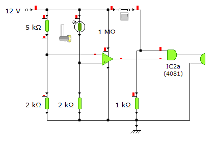
What you should do instead is use two voltage dividers - one with fixed resistors* and one made out of a fixed resistor and the LDR. Like this:

Now, when the resistance of the LDR gets lower than 5k Ohm, the voltage on the "+" input of the opamp becomes higher than the voltage on the "-" input and the output goes high, turning on the buzzer. In real life you would want to replace the fixed 5k Ohm resistor with a potentiometer, so you could set the light level at which the buzzer turns on.
Also, as you see, I connected a 1kOhm resistor from the switch to ground, so that when the switch is open, the input of the gate is grounded. You also may need to use a transistor to drive the buzzer, depending on how much current it uses (in reality).
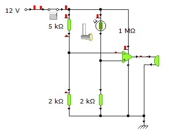
However, your circuit can be made simpler if the switch just turned off the power supply, like this:

Again, in real life you may need to use a transistor if the buzzer uses too much current.
Now the switch turns off the entire circuit so the buzzer will not sound. For some weird reason though, Yenka simulates this as if the buzzer sounded briefly while the switched was turning off, but in reality it would not happen :)
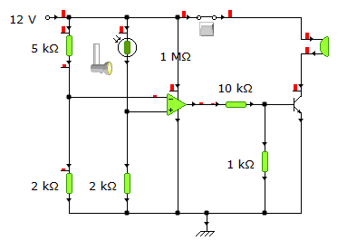
If, for some reason you want the opamp to remain powered at all times, you can use the switch to disable the buzzer like this:

I also added a transistor here, since it is needed :) Because the opamp outputs 2V while it is "off", I added a voltage divider so the transistor does not turn on when it should not. If you were connecting this to the ouput of the AND gate, only the 10k resistor would be required.


