1
\$\begingroup\$

I am trying to build an RFID system to track animals. I am using 125 Khz glass capsule tags by Sparkfun implanted under their skin. I initially used an ID-12LA reader, but I am not getting reads most of the time, possibly due to tag angle, tag orientation, read range...etc.

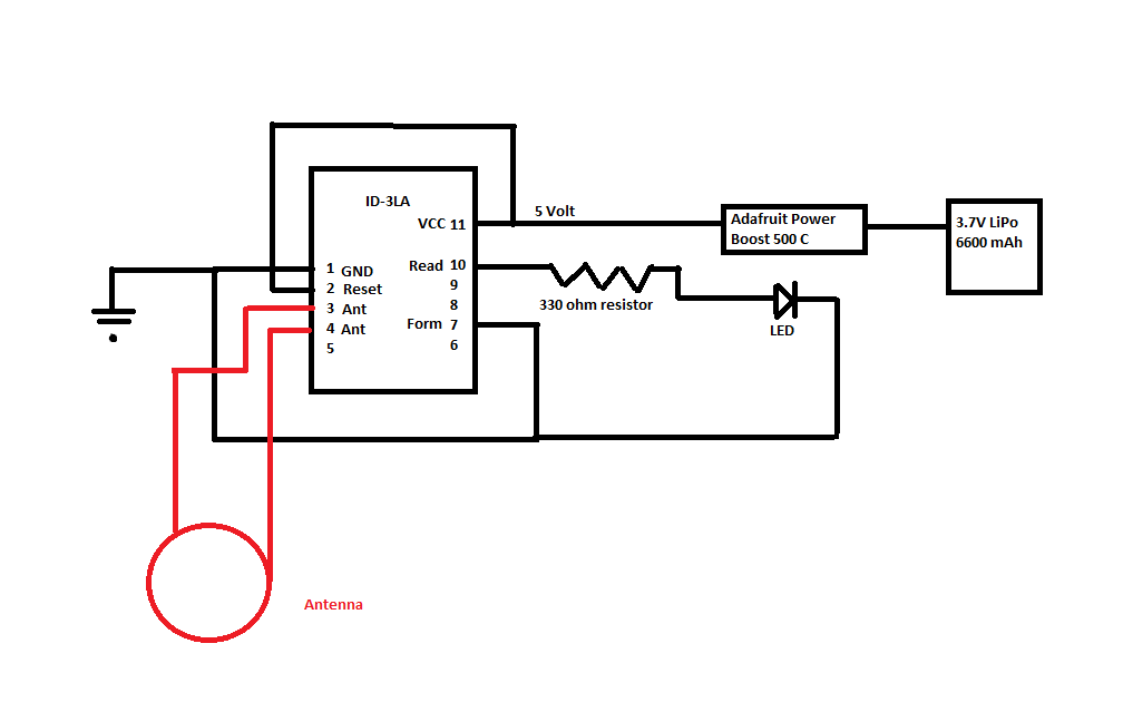
I am moving on to an ID-3LA in order to utilize its external antenna capabilities. This reader requires an antenna producing 1.337 mH. So, I bought a 46 mm antenna capable of producing 2.8 mH. I connected the system as follows:

enter image description here

but unfortunately, I am unable to get reads at all.

Here are my design/troubleshooting questions:

1) In general, if I have an antenna capable of producing inductance higher than that required by the reader, will this compromise the system? If so, what are ways to reduce inductance (without having to remove turns)? According to my research from previously asked questions on this website: people spoke of adding a capacitor to increase inductance but I haven't seen anyone speak of decreasing inductance. Are there any tricks using resistors...etc.?

2) Is there a physical limitation in my system: small tag, antenna with small diameter, read range of 46 mm (or in other words read range inside the circular antenna)? Am I possibly activating the tag, but unable to read it back because of the magnitude of its "identity signal"?

Thanks

\$\endgroup\$
3
  • 1
    \$\begingroup\$ Float like a butterfly, sting like a bee \$\endgroup\$
    – user76844
    Commented May 21, 2017 at 20:36
  • \$\begingroup\$ @GregoryKornblum finally someone on here with a great sense of humor <3 \$\endgroup\$ Commented Jun 25, 2017 at 22:09
  • \$\begingroup\$ Did you have correct size of antenna? In data sheet of ID 3LA, in order to read a glass tags, size of antenna should be 10x10 cm. It seems you have 4.6 cm dia of coil. Also, look for any interference between you object and antenna. \$\endgroup\$
    – CNA
    Commented Aug 11, 2017 at 3:56

2 Answers 2

2
\$\begingroup\$

If you have an LC tank circuit and want to reduce the inductance at resonance:

The inductor you have has inductance of L = 2.8mH:
At 125kHz the inductive reactance is \$\mathsf{2 \pi \, f \, L}\$ = 2199 Ohm.

The inductor you would like to have has inductance of L = 1.337mH:
At 125kHz the inductive reactance is \$ \mathsf{2 \pi \,f \, L}\$ = 1050 Ohm.

So you need to reduce inductive reactance by 2199-1050=1149 Ohm.

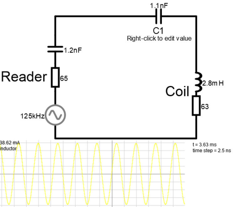
At 125kHz the reactance of a 1.1nF capacitor is \$\mathsf{ \frac {1}{2\,\pi \, f \, C}}\$ = 1157 Ohm, which is within a few Ohms of the 1149 "inductive" Ohms you want to cancel out.

Here's a simple model of your driver, coil and the 1.1nF "canceling cap" C1

In the simulation you can edit (by right-clicking) the value of C1 and observe the effect on the coil current.

Note (in the simulation) that the voltage across capacitor C1 is quite high - make sure you consider the voltage rating of the capacitor you use!

Screen dump of reader and coil simulation

The 63 Ohms of loss resistance in the coil model is probably a low-ball estimate, as inductor losses quickly increase with frequency due to the skin effect.

Finally, you are likely better off (reduced coil loss resistance) by reducing the number of windings on the inductor by (roughly) a factor sqrt(1.337mH/2.8mH)

\$\endgroup\$
0
\$\begingroup\$

Forget that 46mm diameter antenna for reading hypodermic tags. Zoos have a hard time with 200mm diameter antennas and professional readers.

Reducing coil resistance is key. Because the more resistance the coil has, the more it attenuates the incoming field. Also: no iron near the coil as it deforms the field in odd ways.

\$\endgroup\$

Your Answer

By clicking “Post Your Answer”, you agree to our terms of service and acknowledge you have read our privacy policy.

Not the answer you're looking for? Browse other questions tagged or ask your own question.