I am trying to measure the current draw of a digital hobby servo (futaba 3050) to estimate its applied torque.
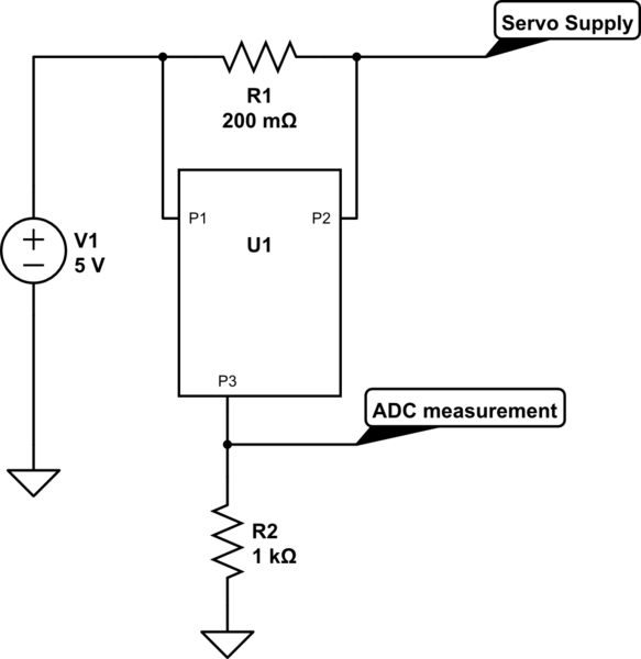
To implement this I am using a shunt resistor setup with an IC that will send a proportional current through its output (P3) which will then be drawn through a resistor (R2) giving a output voltage that will be measurable by the MCU.
(The setup is shown in the schematic below, using a 0.2ohm shunt resistor and the IC ZXCT1009FTA by 'Diodes Incorporated')

simulate this circuit – Schematic created using CircuitLab
After having implemented this on a PCB I have been testing the circuit and I have a few questions regarding my results.
When first testing the circuit I used a simple power resistor to draw a fixed current through the wire called "Servo Supply" in the schematic. And while varying the current from my lab bench power supply through the power resistor the voltage on "ADC measurement" changed proportionally to the current as expected.
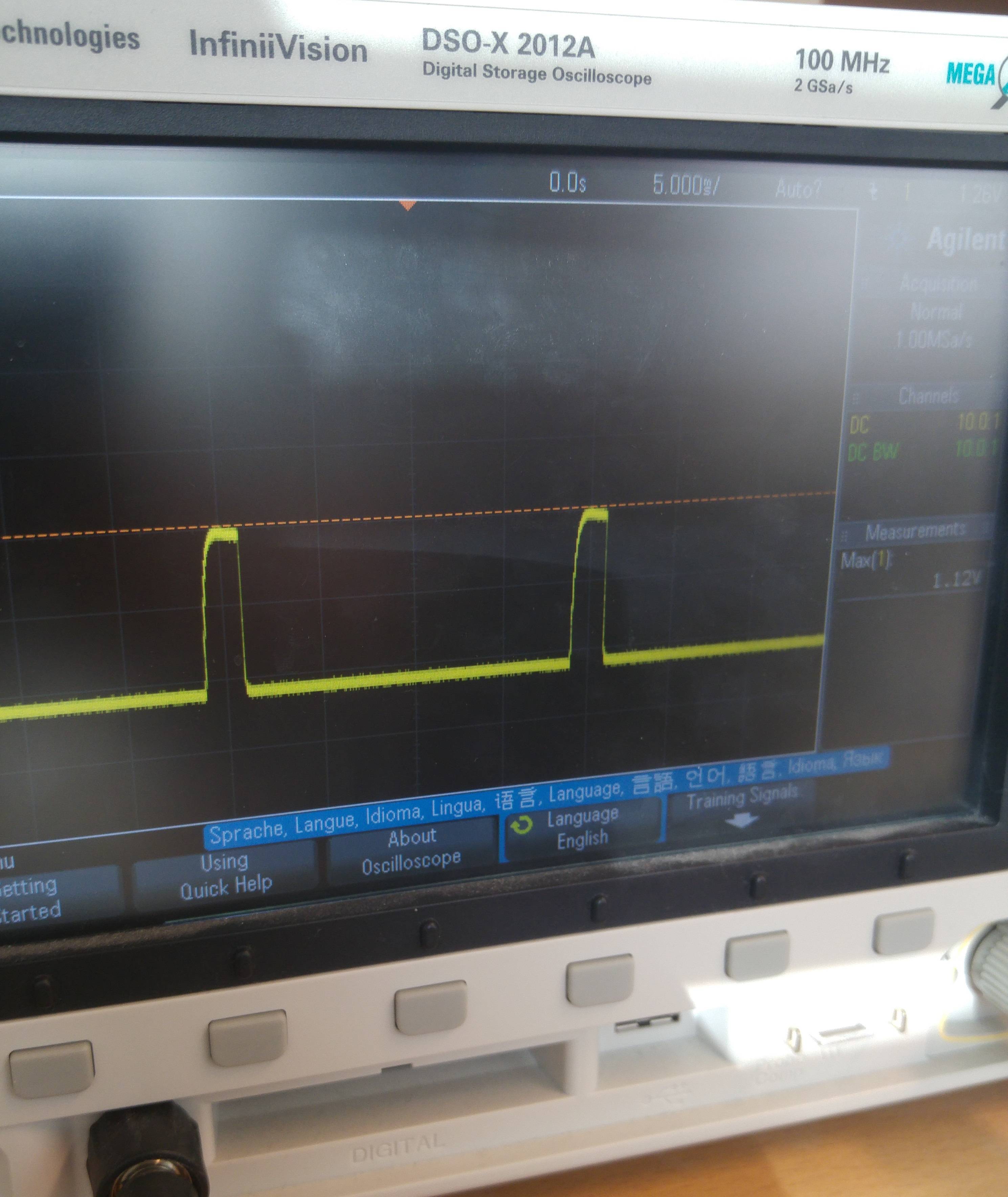
After passing this simple first test I then moved on to the real test, actually running a servo as load. But unfortunately I ran into trouble. I probed the voltage at "ADC measurement" pin. And the result from running the Servo (keeping it at a fixed position but applying small torque) can be seen in the first image.
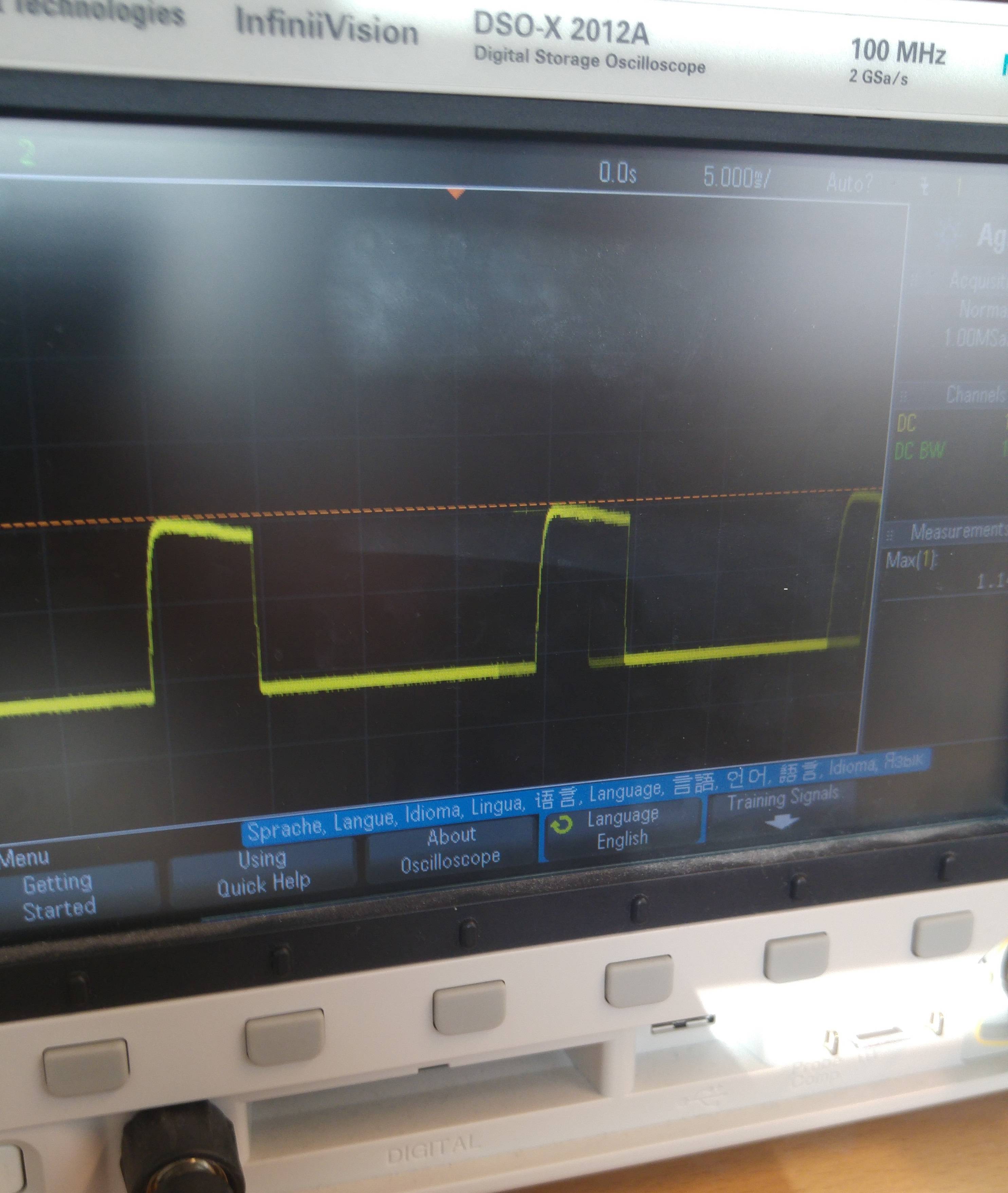
When then applying more torque the measured voltage is kept at the same level but kept high for a longer time. Actually making the current measurement behave like a PWM. Here is another image with more torque applied to the servo.
After searching for more information about doing current measurements on servos I read about this behaviour which I assume is originating from that the servo is controlled with a PWM signal?
So to summarize into the actual question: How will I go about to measure the current (torque) of the servo in a good way? I read about measuring the average current draw for example by adding a capacitor (at the ADC pin I assume), but I feel unsure about how I would choose said capacitor?
Or could I just do ADC measurements and take the average over a full PWM period?
Thankful for any input/help. If there's any additional info needed I am happy to extend the question.
Best regards, Mattias


