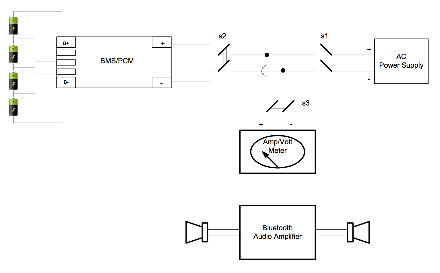
I am building a bluetooth speaker with two power sources: AC power supply and LiPo battery with a charging module (BMS PCM). As you can see from the diagram I have three switches. The goal is to allow for several states:
1. Speaker working on Battery module
2. Speaker working on Power Supply
3. Speaker off, but Power Supply is charging the battery
I don't like the fact that there are three switches for this and the operator has to know different sequences for s1, s2, s3 positions in order to operate the bluetooth speaker. Is there a smarter way to manage this using different logic?

-
\$\begingroup\$ What are you using for a BMS? Does it possibly have an output to provide power to your device? Post a link to the BMS datasheet. \$\endgroup\$– JRECommented Oct 19, 2016 at 12:34
-
\$\begingroup\$ Doesn't the charging module have both an external power input for the AC-DC supply and an output to provide power to your device? It should. For example, this module works like that, and you don't need any switch at all (except one to eventually switch the amp off). \$\endgroup\$– dimCommented Oct 19, 2016 at 12:58
-
\$\begingroup\$ I am using Generic 4s 14.8V BMS PCM battery with balance protection. This is the type: link \$\endgroup\$– vladiatorCommented Oct 19, 2016 at 15:38
-
\$\begingroup\$ dim, thanks for the link to the charging module. It looks like exactly what I need, but I need higher voltage. At least 12V. \$\endgroup\$– vladiatorCommented Oct 19, 2016 at 15:46
2 Answers
-
\$\begingroup\$ Thanks for the comment. I am trying to understand the diagram, but wouldn't the diode on top simply prevent the flow in the reverse direction? \$\endgroup\$ Commented Oct 19, 2016 at 16:04
-
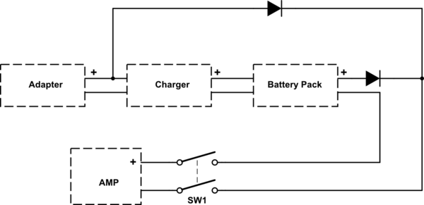
\$\begingroup\$ Sorry for passing your question @vladiator. I should have forgotten. You're right, diodes block the current to flow in the reverse direction. Thanks to this holy property of diodes, the above config simply forms an OR gate: If the voltage on the anode of one diode is larger than the other's then this will conduct and the other one won't. Example: Adapter output is 19VDC and battery output is 14VDC. If the top diode conducts then the voltage on its cathode (and on the bottom's cathode) will be 18.3VDC, so the diode on bottom cannot conduct due to voltage difference across its terminals. ... \$\endgroup\$ Commented Dec 19, 2016 at 4:45
-
\$\begingroup\$ ... Likewise, If there's no line voltage then adapter output will be 0V. Battery pack output was 14VDC, so the diode on bottom will conduct and cathode voltage will be 13.3VDC. Thus, the diode on top cannot conduct due the voltage difference across its terminals. \$\endgroup\$ Commented Dec 19, 2016 at 4:48
Use two diodes to form a diode-oring function between the battery output and the AC adapter output. The system will then draw power from whichever source is at the higher voltage without the user having to do anything. If you want higher efficiency you can use an ideal diode controller. Linear Tech sells lots of them.
One possible option is the LT1760. It includes a lithium smart battery charger and an ideal diode or-ing function all in one chip.
-
\$\begingroup\$ Diode or-ing as you describe wouldn't allow the battery to be charged from the AC adapter. \$\endgroup\$– dimCommented Oct 19, 2016 at 15:07

