1
\$\begingroup\$

I'm working on an automatic door that runs like this:

  1. Receives an input trigger, probably a voltage input
  2. DC motor runs in one direction for x seconds to open the door
  3. Same DC motor reverses direction for x seconds to close the door
  4. Standby for another trigger

The challenge here is that I can't use any microcontrollers (I'm too reliant on those things) and that everything is automated. I've done some research, so I've figured that I can control the motor direction with a H-bridge IC like an L298N, but I'm pretty confused with the timing control.

So far, I've found capacitor and 555 timing control circuits, but they are timing to ON and OFF circuits, which I'm not sure how to fit in here. I've also found a couple of time delay relays, but I don't know how those work.

Any help would be appreciated, thanks!

\$\endgroup\$
5
  • \$\begingroup\$ Why can't you use a microcontroller? \$\endgroup\$ Commented Oct 26, 2016 at 4:52
  • 1
    \$\begingroup\$ Have you looked at commercially available automatic overhead (garage) door openers? These provide motor drive control, as well as safety reverse/shutoff to prevent the door from crushing people. Note that these devices don't run the motor for a fixed time interval, they instead sense the position of the door. When the door reaches the end of its travel, stop driving the motor. May be a good place to start, at least for defining the requirements. \$\endgroup\$
    – MarkU
    Commented Oct 26, 2016 at 5:29
  • 2
    \$\begingroup\$ I agree, the timing idea is a bit flawed. You should think about using limit switches (e.g. micro-switches). One for the closed position and one for the open position. The control will be a lot simpler with these compared to the timer approach. And I dare say a bit more predictable. If the door is being used for human traffic, there are a bunch of safety considerations and regulatory issues, even if it's one-of-a-kind. \$\endgroup\$
    – FiddyOhm
    Commented Oct 26, 2016 at 8:56
  • 2
    \$\begingroup\$ Yes, this application would need either microswitches or a slipping clutch of some type, otherwise the motor is going to be stalling all the time. Actually a clutch might make sense anyway, in case something is in the way of the door completing its travel. \$\endgroup\$
    – Ian Bland
    Commented Oct 26, 2016 at 9:59
  • \$\begingroup\$ Simple method is use limit switches with reverse diode across switch. Motor runs until switch operates. When polarity is reversed diode at that end conducts and motor is driven out of what was dead zone. \$\endgroup\$
    – Russell McMahon
    Commented Oct 26, 2016 at 11:38

1 Answer 1

2
\$\begingroup\$

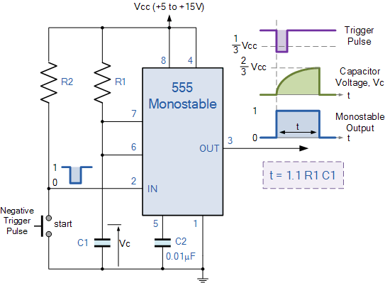
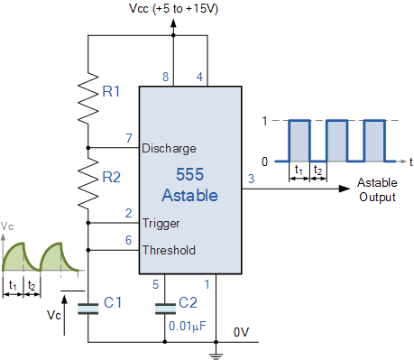
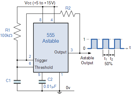
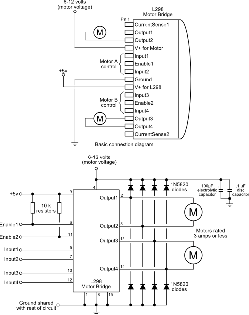
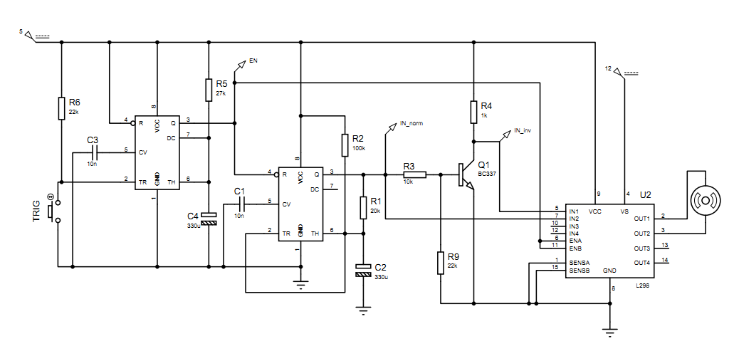
I've built a circuit in Proteus VSM for you. The circuit consists of 3 blocks:

1) A Monostable Multivibrator for managing trigger signals and generating enable signals:

enter image description here

img source: http://www.electronics-tutorials.ws

2) An astable multivibrator for managing open- and close-durations:

enter image description here enter image description here

img source: http://www.electronics-tutorials.ws

NOTE: If you want both durations to be equal then use the following:

enter image description here enter image description here

img source: http://www.electronics-tutorials.ws

3) Motor Driver:

enter image description here

Final circuit (Click for full view): enter image description here

First block is a monostable multivibrator with trigger input and "ENABLE/STOP" output. The output goes directly to the second block's ENABLE/RESET input and the motor driver's ENABLE input. The duration of ENABLE signal is the sum of on- and off-durations: \$T = 1.1 \cdot R5 \cdot C4 = 1.1 \cdot 27k \cdot 330\mu F = 9.8s\$

Second block is an astable multivibrator with equal on- and off-durations: \$T_{on} = T_{off} = 0.693 \cdot R1 \cdot C2 = 0.693 \cdot 20k \cdot 330\mu F = 5s\$.

Third block is a 2-way motor driver. Setting IN1=1 and IN2=0 forces the motor to turn on one direction; likewise setting IN1=0 and IN2=1 forces the motor to turn on the reverse direction.

Here's the Proteus VSM simulation file: http://www.filedropper.com/m_5

\$\endgroup\$
5
  • \$\begingroup\$ Very nice answer. \$\endgroup\$ Commented Oct 26, 2016 at 8:42
  • \$\begingroup\$ I just tried the circuit today (the final image provided) but after 5s of moving in one direction the motor stopped without continuing in the other direction. I didn't find any problems with connections or the motor, so what do you think might be the problem? \$\endgroup\$ Commented Nov 16, 2016 at 5:37
  • \$\begingroup\$ I'm also using an L293D instead of an L298. \$\endgroup\$ Commented Nov 16, 2016 at 5:38
  • \$\begingroup\$ I didn't build the circuit, just made a simulation. You have the Proteus simulation file. Try it with L293D. \$\endgroup\$ Commented Nov 16, 2016 at 7:48
  • \$\begingroup\$ @thefinshark I tried on the simulation with L293D and saw no problem(s). Here's the updated simulation file: filedropper.com/mr Check your supply and cabling. Note that there are 5V and 12V supplies for the circuit. \$\endgroup\$ Commented Nov 16, 2016 at 10:00

Your Answer

By clicking “Post Your Answer”, you agree to our terms of service and acknowledge you have read our privacy policy.

Not the answer you're looking for? Browse other questions tagged or ask your own question.