2
\$\begingroup\$

I am trying to develop a system for bioimpedance measurement.

I will use a frequency equivalent to 50KHz, using this project to support me.

The project uses an instrumentation amplifier. In my city I just found the INA111, but it is a very expensive component, so I decided to make my own instrumentation amplifier using three Op Amps (TL084CN).

I'm using this article to support me Design of an Instrumentation Amplifier - Justin Bauer.

My doubt is:

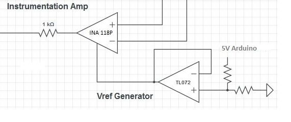
Since the AD5933 can only read positive voltages, an input of 2.5V is connected into the Vref terminal of instrumentation amplifier (INA118P). This is done to 'convert' the AC voltage to DC (I think).

instrumentation amplifier

How do I do that? If I do not have terminal Vref on my "home Instrumentation Amplifier"?

Sorry, my English is bad (I'm not American), and I'm starting with electronics.

\$\endgroup\$
3
  • \$\begingroup\$ You do have a ref terminal on your homebrew inamp. It's the ref of the output diffamp. How about you post a schematic of what you're intending to brew, then we can point it out. Might be able to point out a few other things as well if you include the whole circuit, so power supply, input biassing. You have a valuable resource here, might as well mine it for what you can. \$\endgroup\$
    – Neil_UK
    Commented Oct 29, 2016 at 5:25
  • \$\begingroup\$ The TL084 may be too noisy for your application. Try to get a less noisy part, for example the TL074 should be in the same price range and has similar specs otherwise. Or use two TL072, since you already have one in your bill of materials. \$\endgroup\$ Commented Oct 29, 2016 at 6:31
  • \$\begingroup\$ Categorically, a three op amp formulation will not give you the CMRR of the most inexpensive off the shelf op amps \$\endgroup\$ Commented Oct 30, 2016 at 22:05

2 Answers 2

2
\$\begingroup\$

The "vref" input of a instrumentation amplifier is just a DC offset on the output. Its use here doesn't convert AC (oscillating) to DC (steady) voltage, but just adds a DC offset to the waveform so that it is oscillating between (say) +3V and +1 V, rather than between +/- 1V.

You can see how it works in the datasheet of the INA118: http://www.ti.com/lit/ds/symlink/ina118.pdf, which shows the standard 3-opamp schematic, including the vref input. I googled the reference you mentioned: http://www.egr.msu.edu/classes/ece480/capstone/spring15/group05/uploads/4/7/5/1/47515639/ece_480_app_note_justin_bauer.pdf here, it is just shown using ground as the reference voltage, but that is easily changed: disconnect R2 from ground, and connect it to your desired reference voltage.

\$\endgroup\$
0
\$\begingroup\$

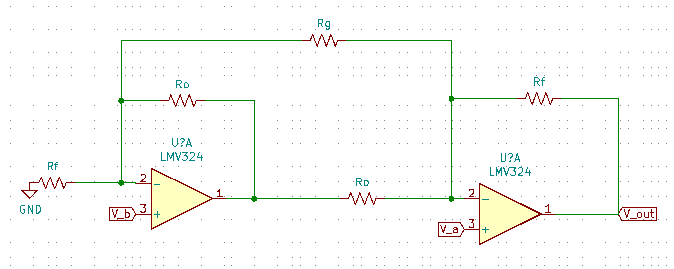
A cheaper instrumentation amplifier can be designed by using only 2-Op Amps + 5 resistors, in place of the conventional 3-op amp + 7 resistors design . Of course, you would have to compromise on the CMRR .This can be done by following the schematic as shown below.

2-op amp based instrumentation amplifier

From simple KCL equations at inverting terminals of op-amps , we can get the equation for

Vout = (Va-Vb)(1+[Rf/Ro]+[2Rf/Rg]), where Rg is the gain tuning resistor used.

Using such a scheme may help in in cases where cost of IA being designed is an issue, but CMRR is not very stringent.

\$\endgroup\$

Your Answer

By clicking “Post Your Answer”, you agree to our terms of service and acknowledge you have read our privacy policy.

Not the answer you're looking for? Browse other questions tagged or ask your own question.