7
\$\begingroup\$

I'm looking to build a dual-rail, regulated, 18VDC power supply based on the 78xx and 79xx regulators. The circuit is inspired by AMB Audio's sigma25 (amb.org/audio/sigma25/) and sigma26 (amb.org/audio/sigma26/) regulated power supplies. I have also Googled around and came across these:

  • eleccircuit.com/wp-content/uploads/2008/10/dual-variable-regulator-power-supply-5-25v-by-lm7805lm7905.jpg
  • eidusa.com/Interface_Boards_PN15_PS.htm

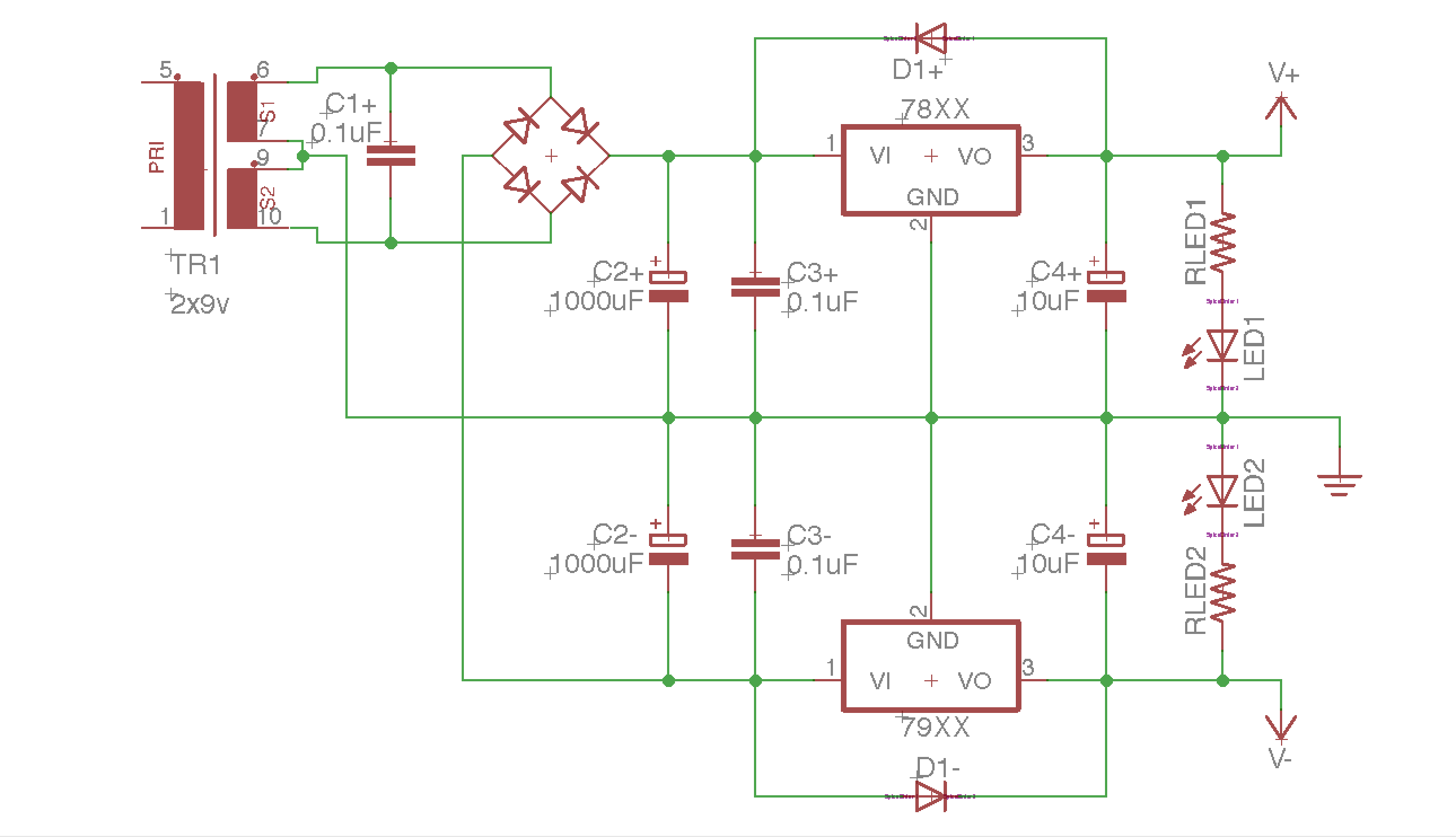
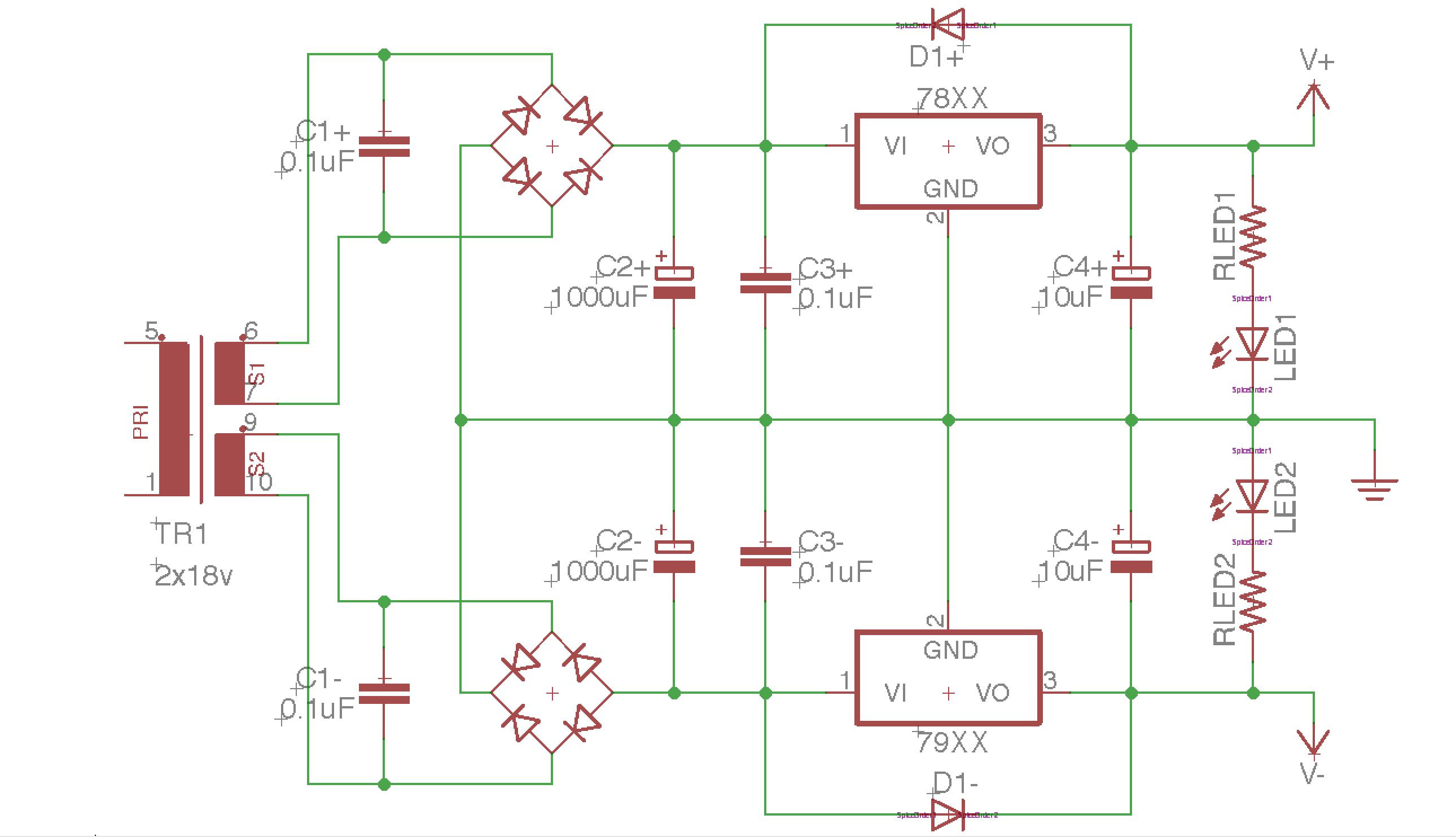
However, I am torn between using a 2x9V transformer and connecting the secondaries as such, using only 1 bridge rectifier to supply both regulators: 2x9V, center-tapped secondaries ...and using a 2x18V transformer, each secondary feeding its own bridge and regulator, as such: 2x18V What are the pros and cons between the two, apart from (slightly) more parts count in the latter schematic?
Many thanks for any enlightenment given.

\$\endgroup\$
1
  • \$\begingroup\$ You might want to put caps across each of the bridge diodes which would accentuate the parts count difference. I don't think C1 is necessary. For a general purpose supply the second configuration would be preferred, but audio has guaranteed almost equal loads on each supply so it's a special case. \$\endgroup\$ Commented Nov 1, 2016 at 11:13

2 Answers 2

5
\$\begingroup\$

As drawn, the 2x9v transformer gives +/- 13 ish v pre-regulator. The 2x18v gives +/- 26v. Once you've sorted out like for like with the transformers (your use of a factor of 2 between the voltages clearly shows that was what was intended), then you can read the rest of the answer that I wrote before I thought about your transformer configuration.

The first diagram with the single bridge rectifier has a slightly higher pre-regulator voltage, as there is only a single diode drop rather than 2 in series.

This means as the mains fluctuates lower, or as the temperature of the transformer (and so its resistance) increases, or as the load current increases, there will be more headroom in hand on the regulators, so they will stay in regulation for a bit longer.

OTOH, the regulators will have to deal with a slightly higher voltage drop, and so get hotter, which is a disadvantage in hot conditions or high mains voltages.

For the same loading conditions, the first design has more dissipation at the regulators, the second has more dissipation at the diodes.

Neither of these advantages or disadvantages are fundamental, and can be designed with, they are only relevant if you have already got the transformer and the output voltage.

There are theoretical cross-regulation issues, but their effect is vanishingly small, and completely irrelevant (unless you are hyping your £3000+ magic HiFi)

I'd go for the lower parts count.

\$\endgroup\$
1
  • \$\begingroup\$ I will keep the heat dissipation in mind. The regulators would be heatsunk and the whole shebang run in an airconditioned room (18 deg Celcius). And no, I'm not running some expensive Hi-Fi off this PSU, merely a humble opamp-based audio amplifier :) Thanks for the suggestion! \$\endgroup\$ Commented Nov 1, 2016 at 7:26
6
\$\begingroup\$

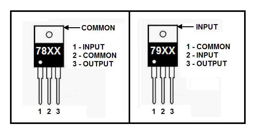
Watch out for that treacherous 79XX pinout!!!

It's wrong on your schematic.

enter image description here

\$\endgroup\$
2
  • \$\begingroup\$ Oops. I'll make sure to wire it the right way when assembling the PSU. Thanks for the heads-up! \$\endgroup\$ Commented Nov 1, 2016 at 9:41
  • \$\begingroup\$ Good catch, the OP's schematic symbol for the 79xx is actually wrong- that should be fixed. \$\endgroup\$ Commented Nov 1, 2016 at 11:08

Your Answer

By clicking “Post Your Answer”, you agree to our terms of service and acknowledge you have read our privacy policy.

Not the answer you're looking for? Browse other questions tagged or ask your own question.