3
\$\begingroup\$

I am building a heart rate monitor using the INA122. In these cases, my electrodes are attached directly to the skin, meaning that above 1mA of output current, I could feel pain from electrical current.

I know that the INA 122 has an input bias of 10 nA for its inputs, but I would like to calculate the current running into its reference terminal. The reference terminal is a 3rd electrode also attached to the skin that aids in noise reduction -- if you've never done biomedical workbefore, think of it as a floating offset voltage. What is the best way for me to calculate, on paper, the current flowing into the reference terminal? Specifically, the current flowing into my reference electrode? The reference terminal appears as "ground" for the single supply case being considered here.

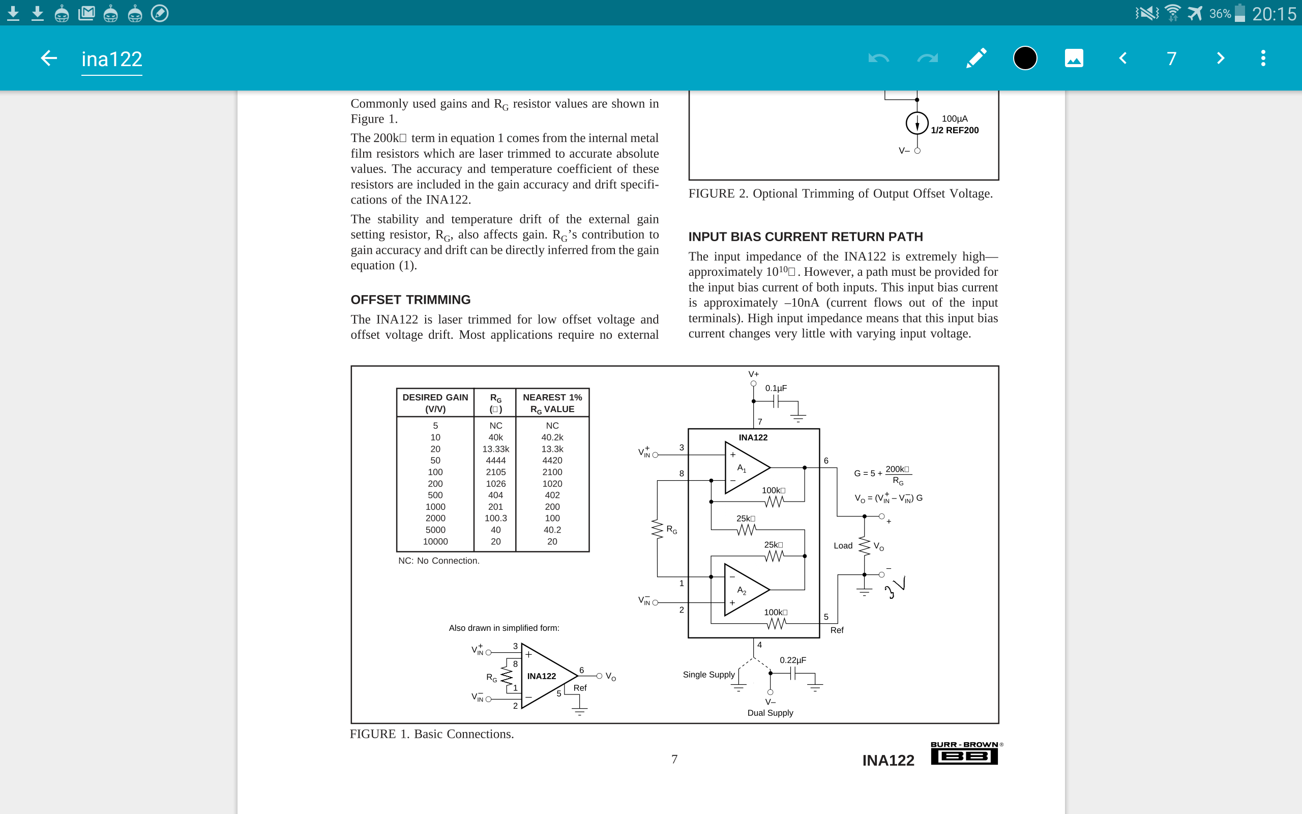
ina 122 description

One of my problems in just doing this by hand is that the positive supply voltage isnt connected to the rest of the circuit? Or rather, it's connected only by a 0.1 uF capacitor. I know this must be a noob question, but how can I calculate the current flowing from the battery to the reference terminal/electrode, since this is likely the bulk of the current entering? Is this even safe to do in the INA's single supply case, where reference and the negative terminal of the battery are shared?

\$\endgroup\$

2 Answers 2

5
\$\begingroup\$

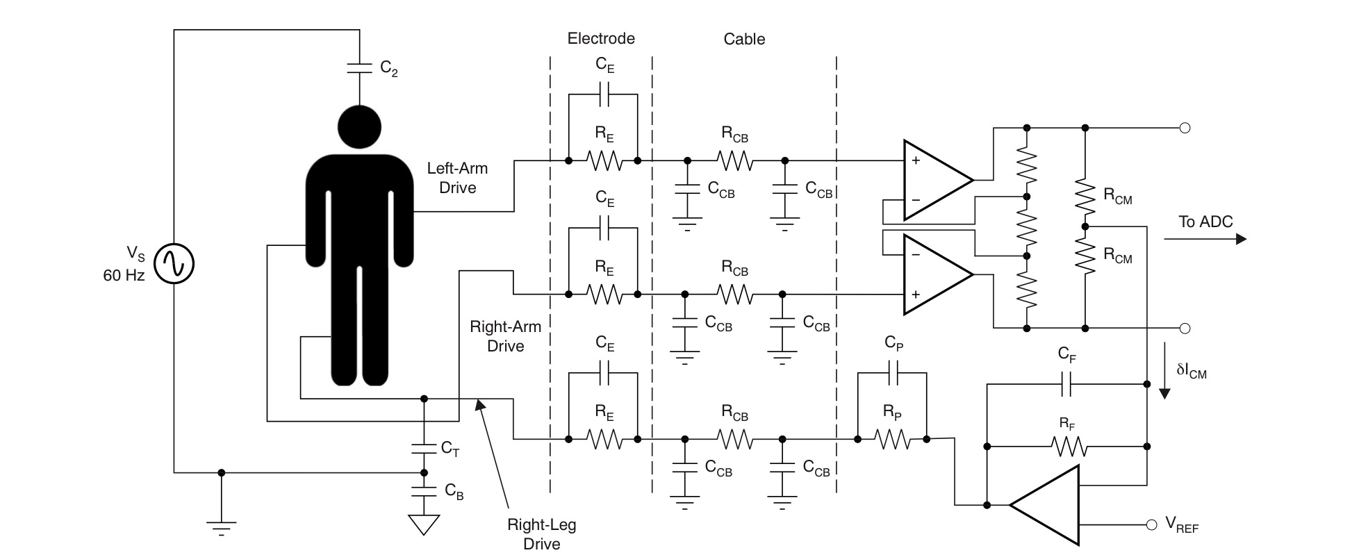
The common mode voltage of the inputs is normally established with a right leg drive amplifier output. Or a resistor to a voltage well within the common mode range of the inputs. It has to supply the total bias current of the two inputs plus any leakage (which must be very low for safety) plus AC pickup from the mains (perhaps 20V VAC through 100pF, so less than 1uA).

You do not directly use the reference pin on the inamp- it is a low impedance pin and should be connected to the circuit common or another 'stiff' voltage source in order to determine the midpoint of the inamp output voltage,

More in this TI document.

enter image description here

Just to be clear, the 100pF caps C2 Ct Cb and the AC 60Hz (or 50Hz maybe) voltage is to model stray capacitance picking up mains voltage. An objective is to minimize such interference with the signal, and since the pickup is large voltage (volts) relative to the signal (mV) common mode rejection is important. They are not physical components you would add- they are undesirable parasitic effects like the Re/Ce of the cables.

In the case of using an inamp you can draw the common mode signal by splitting the gain resistor, which isn't quite as good (see the AD620 datasheet).


Make sure you address safety issues exhaustively- your circuit should certainly not be capable of putting anything like 1mA through the victim patient, even in the case of a failure.

\$\endgroup\$
12
  • 2
    \$\begingroup\$ plus 1 for the attempt at humour \$\endgroup\$
    – Andy aka
    Commented Nov 5, 2016 at 13:15
  • 1
    \$\begingroup\$ @Andyaka, Spehro, yer both twisted. C2 interests me in Spehro's answer - "60Hz-to-the-head". Is this an attempt at left/right tomography? TI should be ashamed - use this circuit with care! \$\endgroup\$
    – glen_geek
    Commented Nov 5, 2016 at 13:55
  • \$\begingroup\$ @glen_geek (heh) This is a circuit attempting to model what is going on.. the 60Hz is capacitive pickup of mains voltage floating around the environment (the capacitors are not physical caps- the 60Hz is assumed because the authors are US-based). Similarly, the Re/Ce are to model the cables running to the electrodes. \$\endgroup\$ Commented Nov 5, 2016 at 14:11
  • \$\begingroup\$ Most of the current the RL driver supplies is because of the capacitive pickup, so to evaluate performance of different circuits you have to model it plausibly. \$\endgroup\$ Commented Nov 5, 2016 at 14:19
  • 1
    \$\begingroup\$ @Kevin, both INA122 inputs have transistor & diode junctions directly to DC supply voltages - your safety concerns should consider what happens when these fail shorted. Fixed resistors in series with electrodes would be prudent. 10nA bias current must flow through these resistors, creating undesirable DC offsets, so they can't be made too large. (data sheet suggests bias current might be as great as 50nA). \$\endgroup\$
    – glen_geek
    Commented Nov 5, 2016 at 15:17
0
\$\begingroup\$

The current generated by the Common mode driver electrode is simply the stray CM E-Field current = Icm = Vcm/Zt where the Zt is the transfer impedance of a series stray voltage with the shunted currents of unknown stray fields balanced or not onto balanced differential signals. (line Vac, RF and ESD)

Although commonly done for cable TV and RF, the same principle applies to shielded differential EMG/EEG/EKG signals..

The concept of Icm is simple but the calculations are not due to the two unknowns, Vcm and Zt. Although the CMRR for low and high frequencies can be predicted and measured.

Here is how it is done simpler for RF on coax.

https://interferencetechnology.com/wp-content/uploads/2012/03/Mardiguian_DDG12.pdf

Ultimately it is done by Test and measurement verification of the design after specs are written with measured E fields scanned over the entire range in a controlled environment. ( i.e. low EMI) by measure immunity to all types of interference, line, RF and impulse fields.

The other specifications required are immunity to defibrillator impulses

  • to prevent damage, which like ESD, except a much bigger C value (Q=CV).

Not read , but here is another reference. with excerpts below.

"Each medical device has a classification/rating of Type B, Type BF, or Type CF. These classifications affect how the device is designed and used. Different leakage current limits and safety testing apply per IEC60601-1. The IEC standard also defines an applied part as the part of the medical device that comes into physical contact with the patient in order for the device to carry out its intended function."

.

"Common-mode rejection can be measured many ways. In this paper, two methods are discussed. The first is to tie all of the ECG electrodes together and drive the electrodes relative to the ECG analog front-end voltage reference."

.

"Another method of measuring common-mode rejection is to tie all the electrodes together and drive them relative to earth ground. Again, the definition of the common-mode rejection is 20×log (V OUT /V IN ), where V IN is the common-mode drive signal and V OUT is the signal seen on the particular lead of interest."

\$\endgroup\$

Your Answer

By clicking “Post Your Answer”, you agree to our terms of service and acknowledge you have read our privacy policy.

Not the answer you're looking for? Browse other questions tagged or ask your own question.